Time for some updates again

it's going to be a long and picture heavy one.

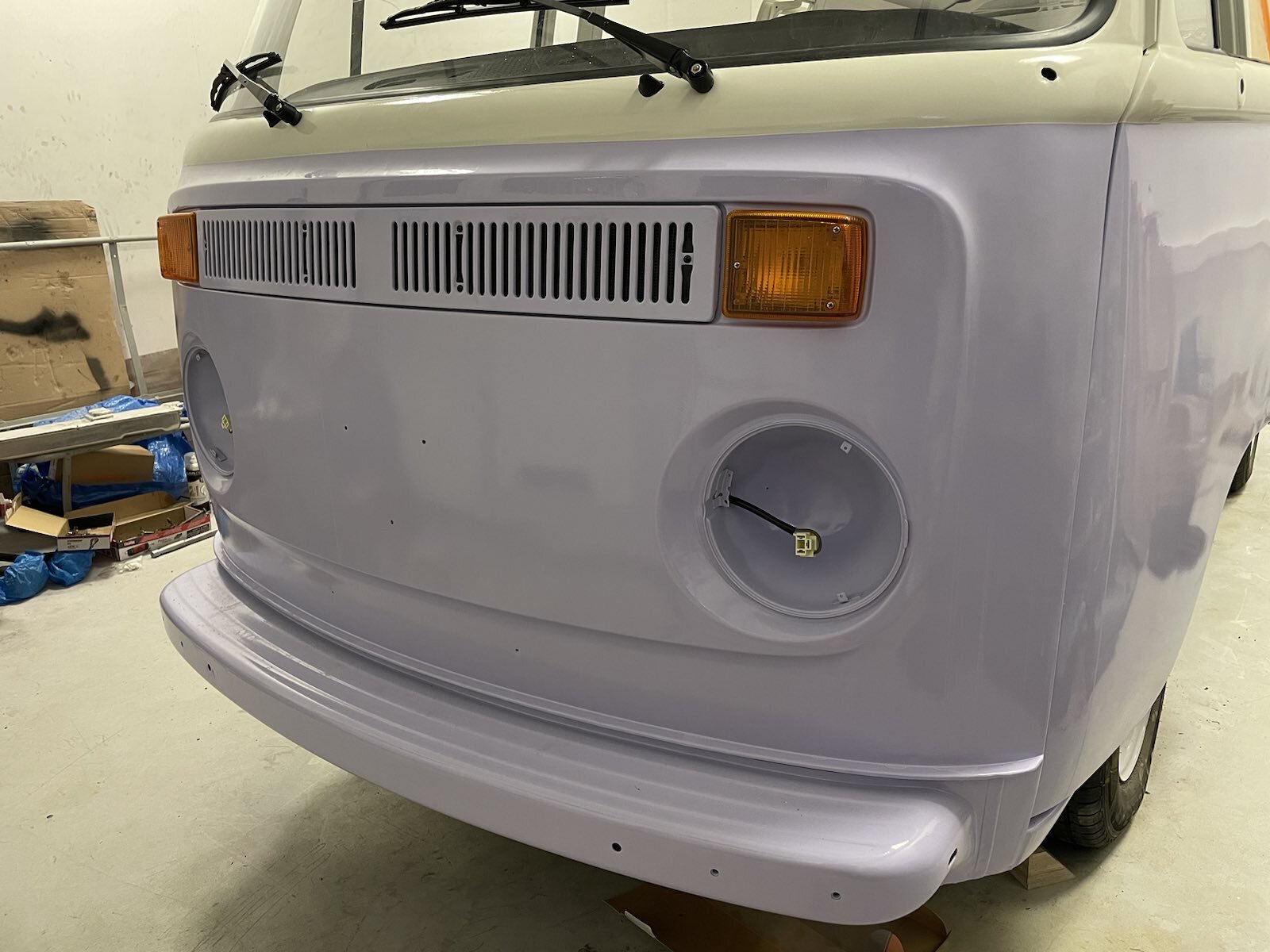
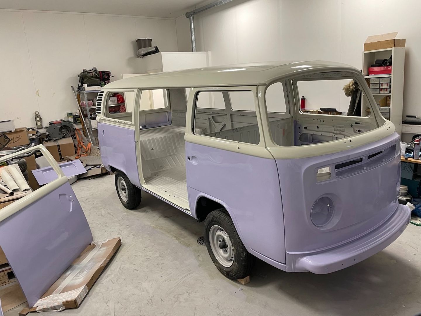
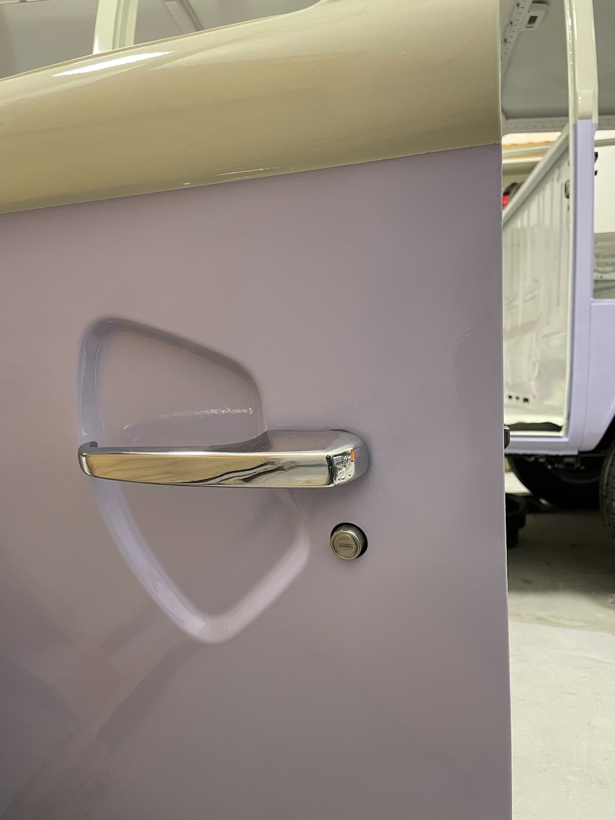
Normal restoration stuff is still taking most of the time, but now I have windshield, doors, dash, seats and all the car stuff mostly in place.

Now it looks like a proper car!
AC is working. There was some of the plastic hinges missing so I designed and made my own, files:
https://www.thingiverse.com/thing:6563627
https://pixelfed.fi/storage/m/_v2/53013 ... yMZtj7.mp4
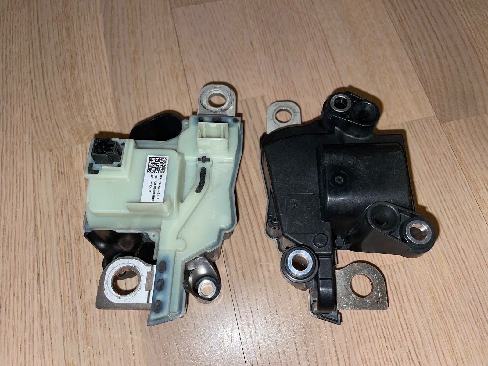
Also the original design for the windshield washer fluid uses pressure from the spare tire to move the fluid from the reservoir to the washer stalk, which acts as a valve, so when you pull the stalk spare tire pressure pushes the fluid through and onto the washer jets. I'm not too keen on the idea of having fluid where my ignition switch wiring is going to be (and 10cm from my fuse box) nor do I want to play around with the spare tire for pressure.
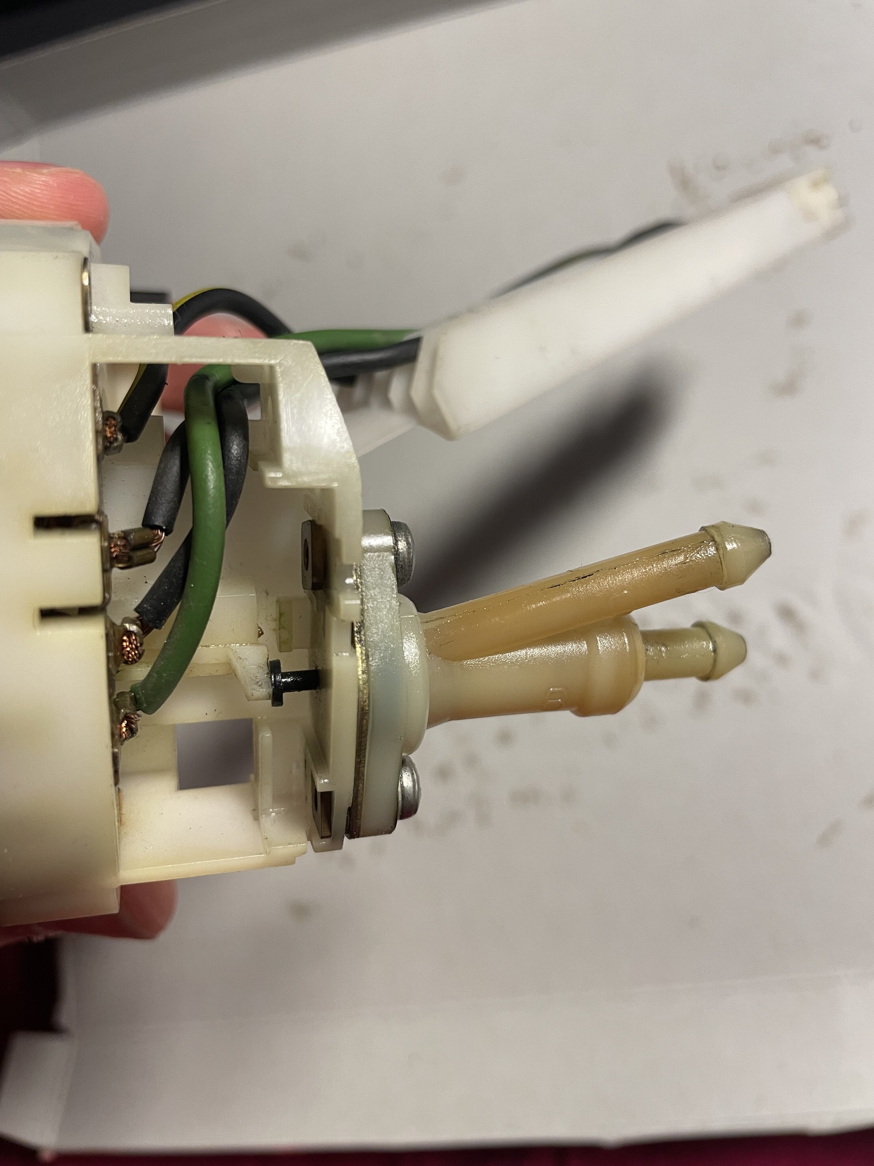
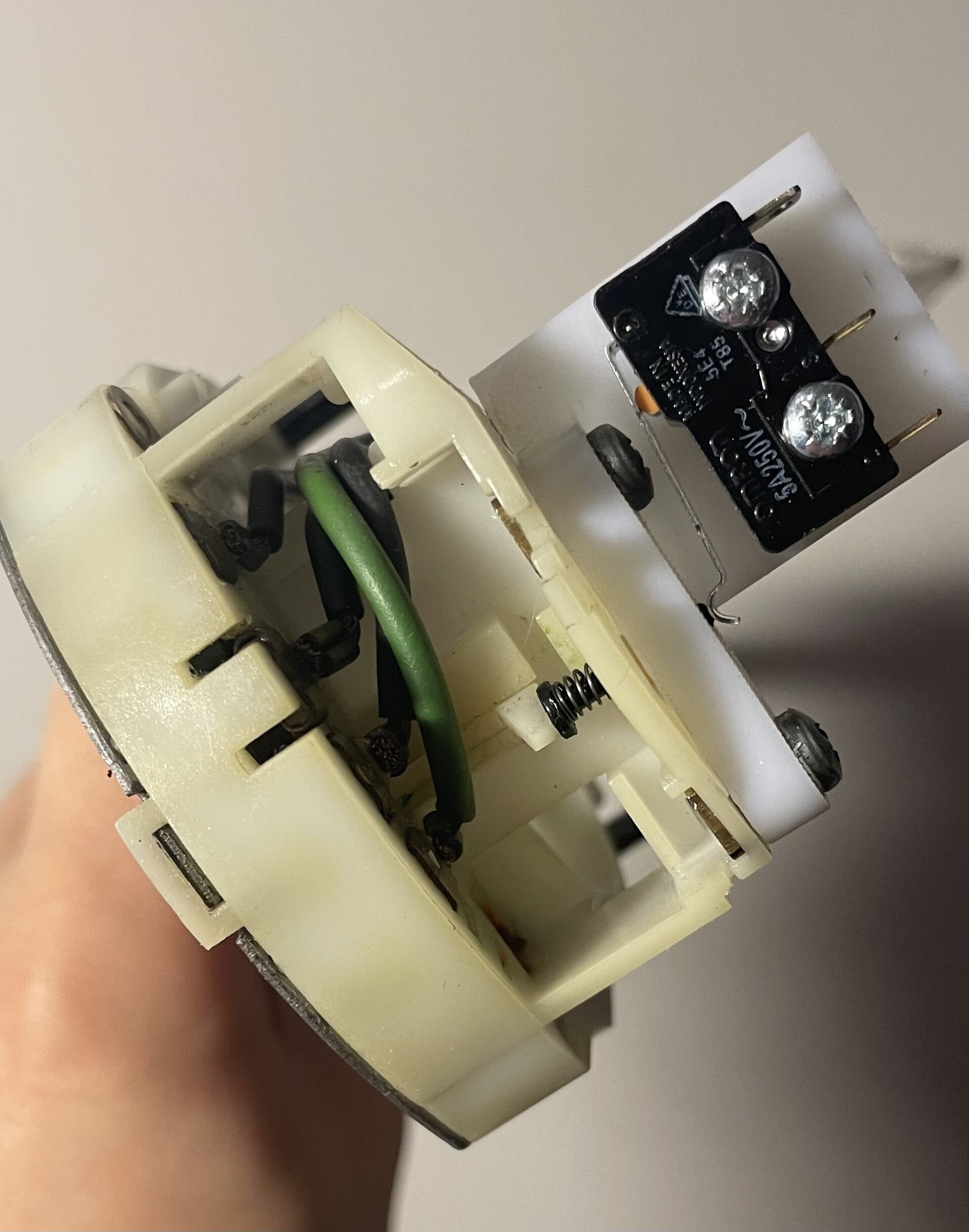
So I removed the valve, kept the black small piece in the middle which the stalk presses onto when pulled, and designed a bracket to accept a microswitch in its place. Files:
https://www.thingiverse.com/thing:6561358
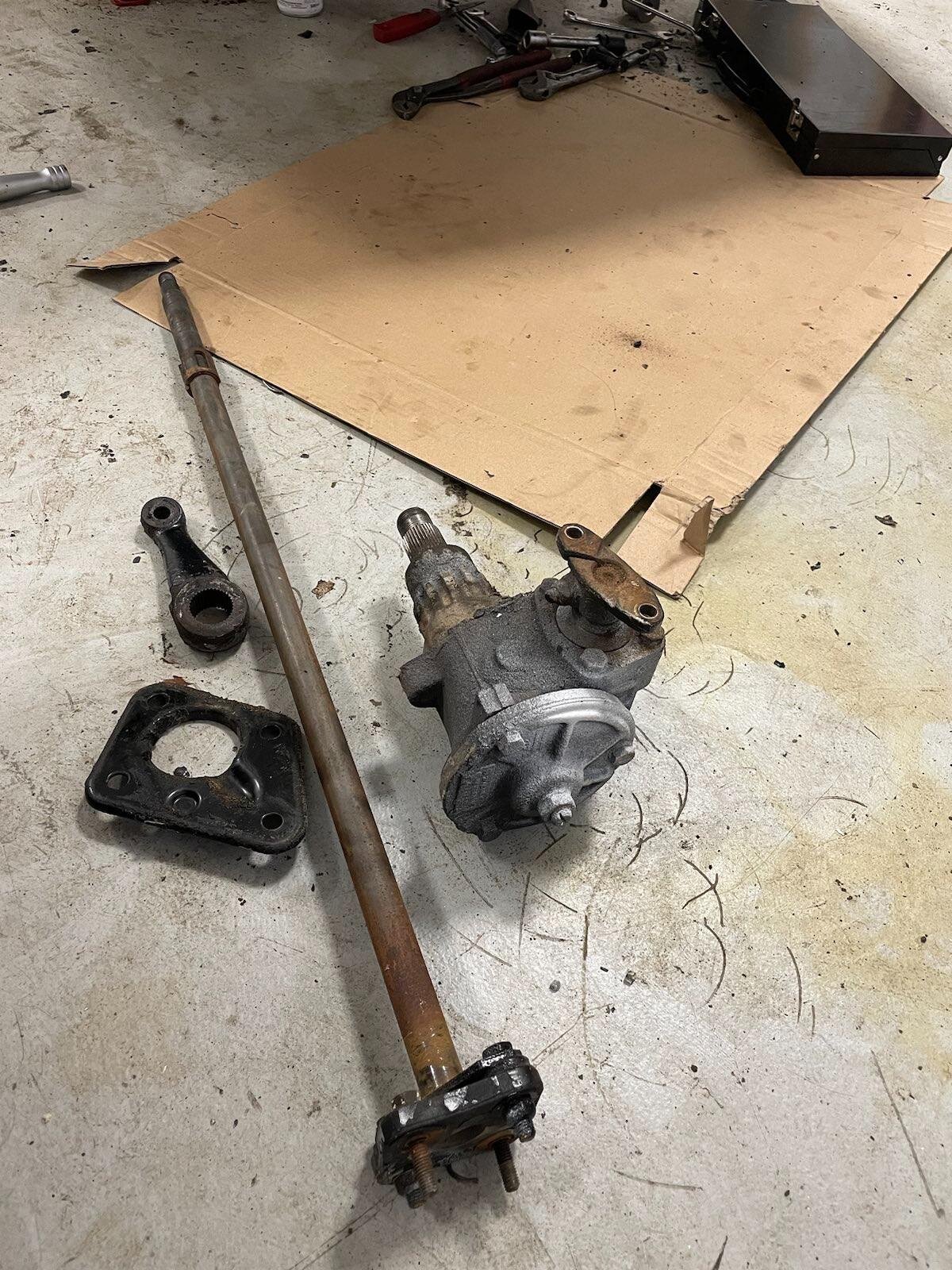
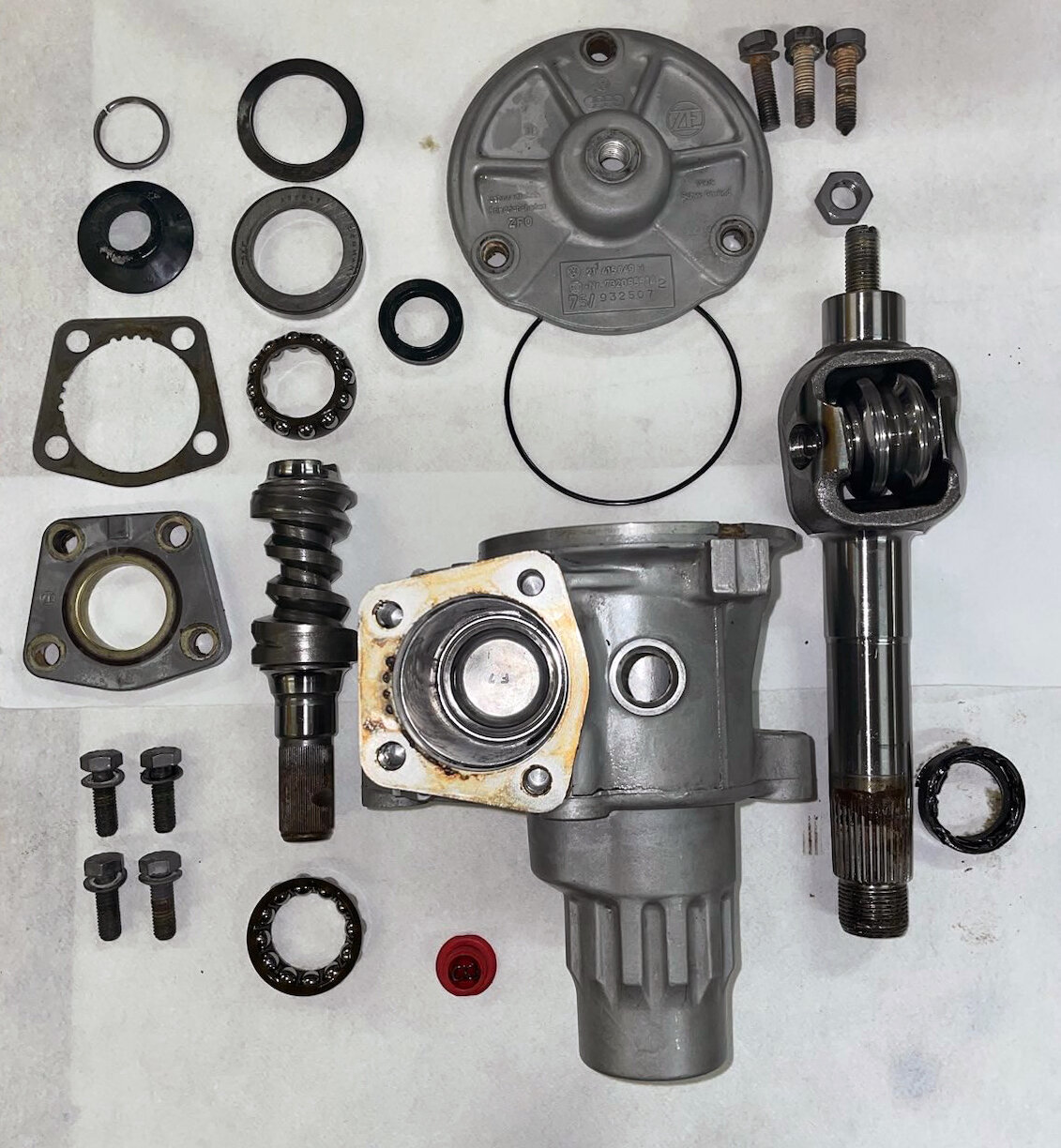
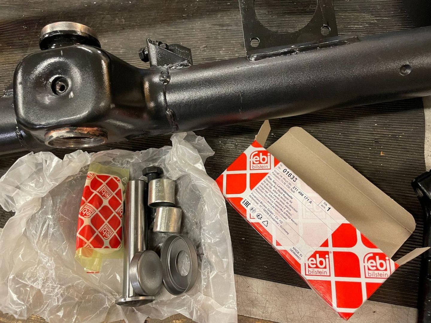
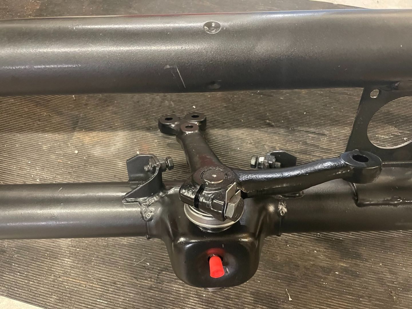
Put the steering box back together, designed a new dust shield to replace the cracked old one, printed out of flexible FPU. Files:
https://www.thingiverse.com/thing:6568166
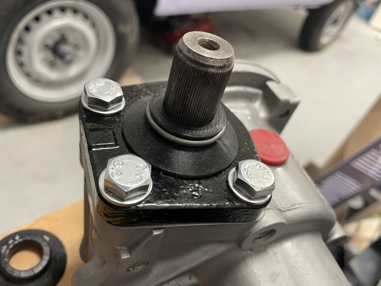
Steering works
https://ceravyn.net/up/VW/IMG_4220.mp4
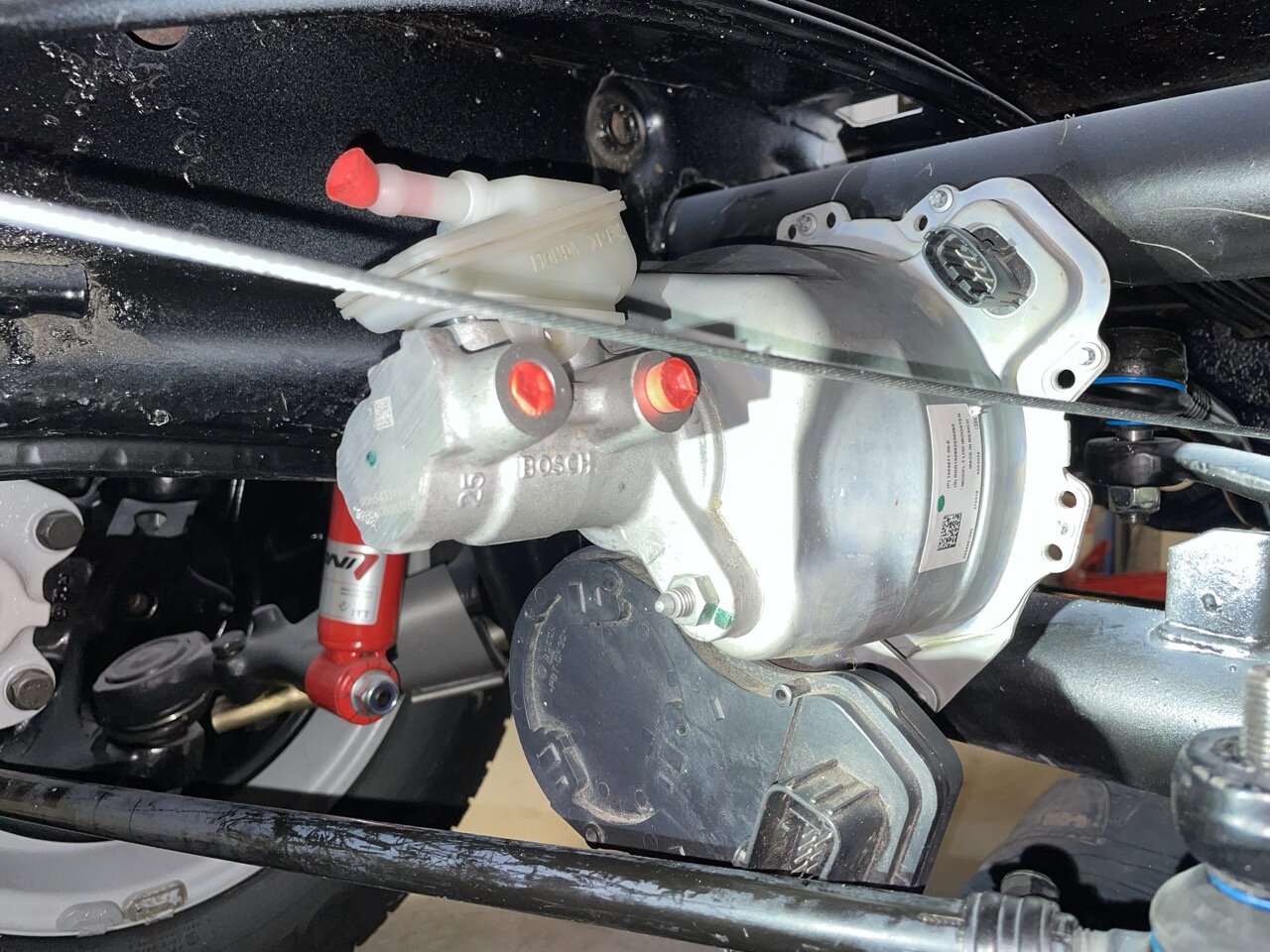
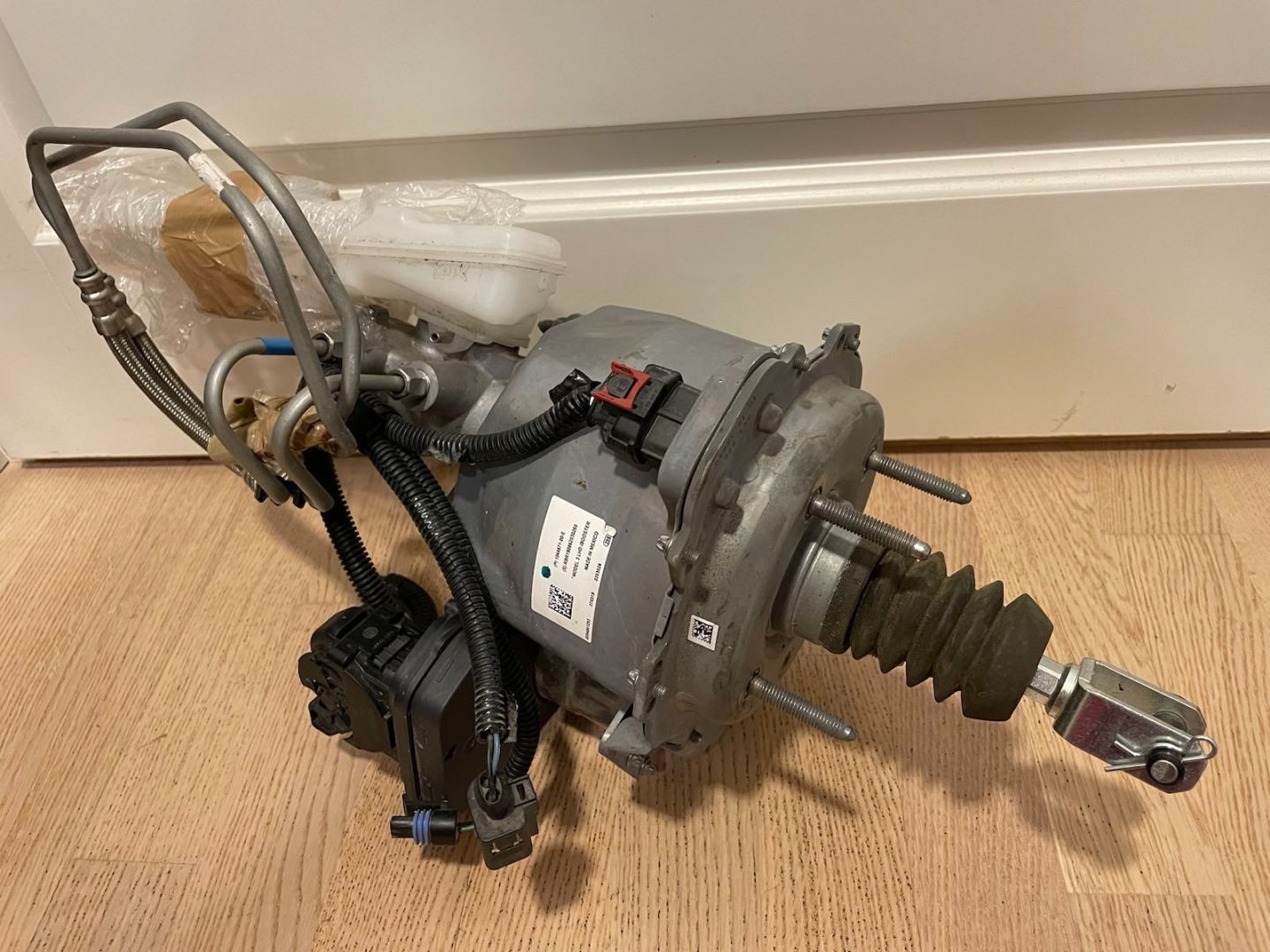
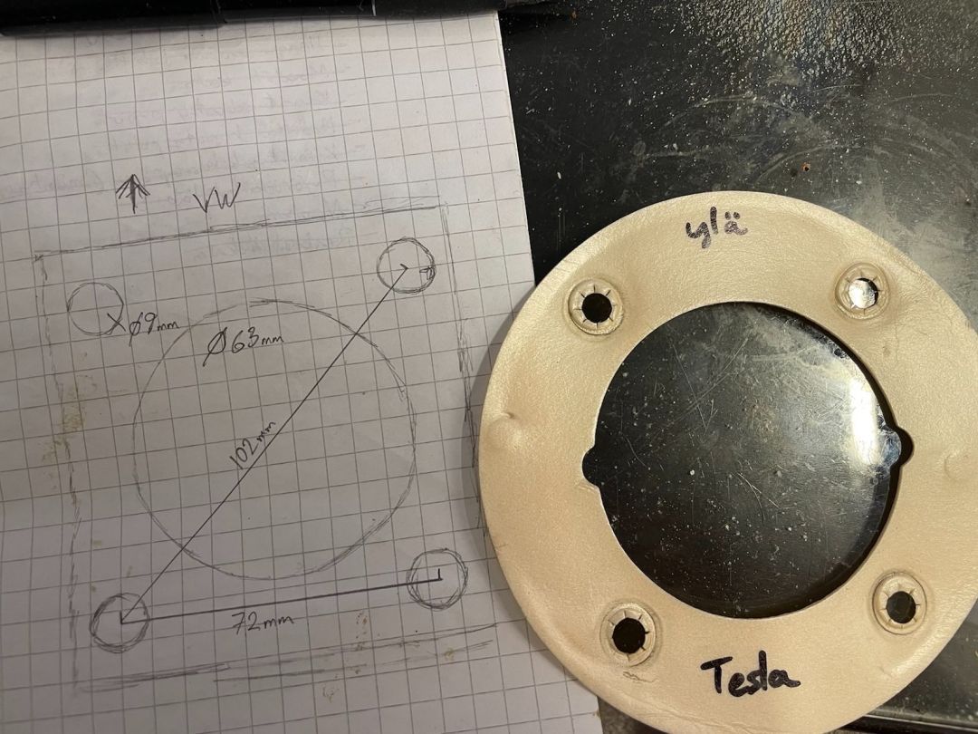
iBooster also found its place finally thanks to help from alexbeatle here.

Bought the two-piece reservoir
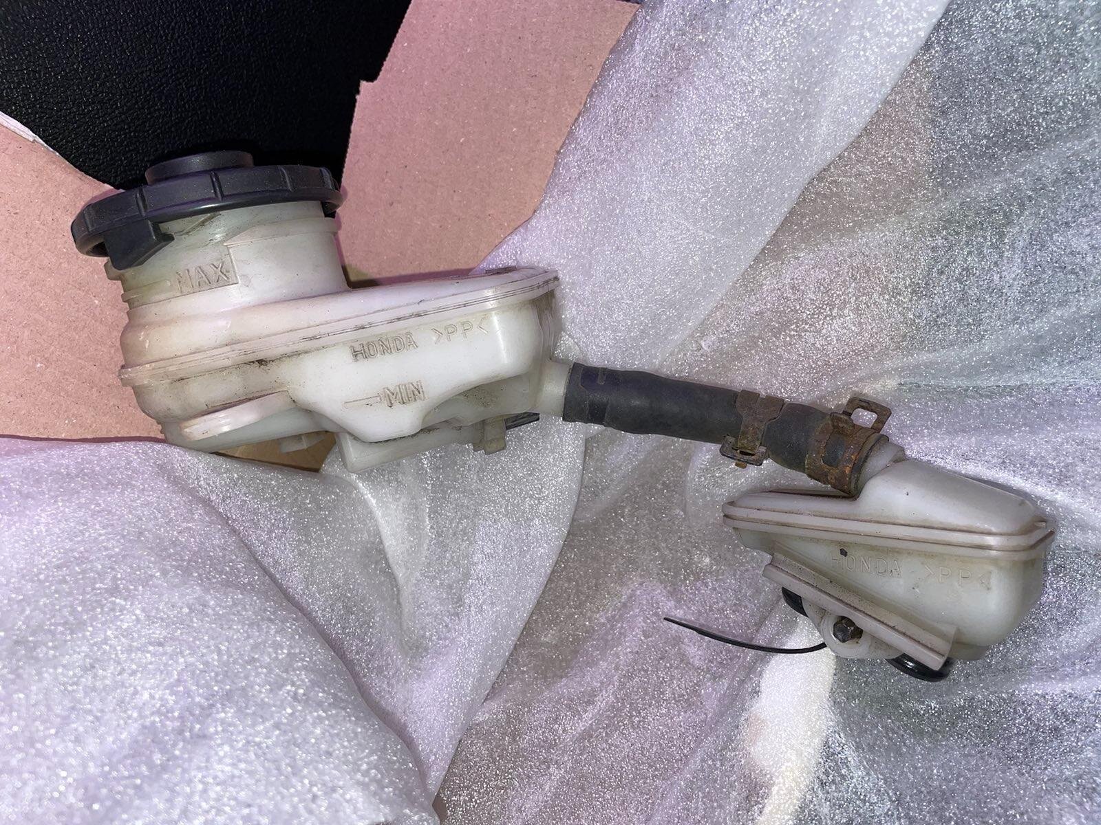
Widened the bolt pattern with a file juuust about 2mm and mounted the thing in there. Just to find out that the tie rod conflicts right where the motor connector is.
There's no steering with this!
I considered rotating the motor somehow to have the connectors facing the other way, but that'd have required manufacturing a new metal plate it mounts to.
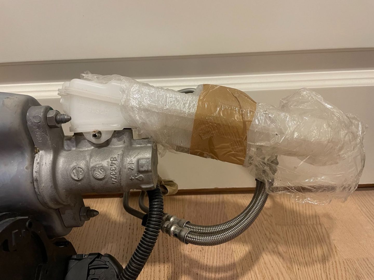
So I just unbolted the master cylinder (it's symmetrical mount and only has the round piston pushing on it from inside the booster) and installed it "upside down".
Then turned the whole thing 180° and now it looks like it was meant to fit there.
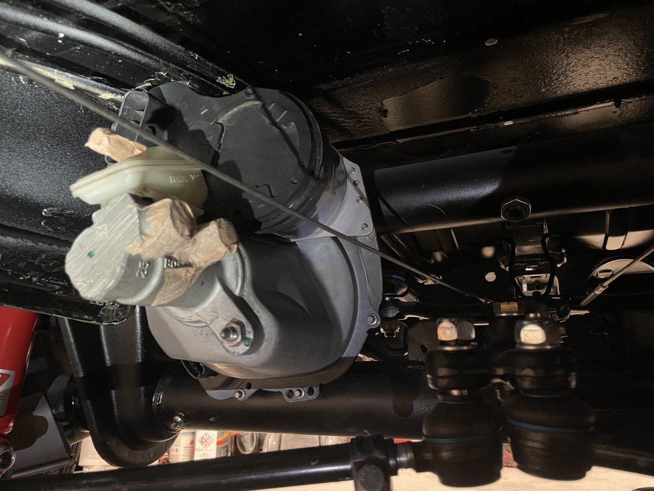
The connectors are now safely above all the moving parts and shielded from the road debris by the booster bulk.
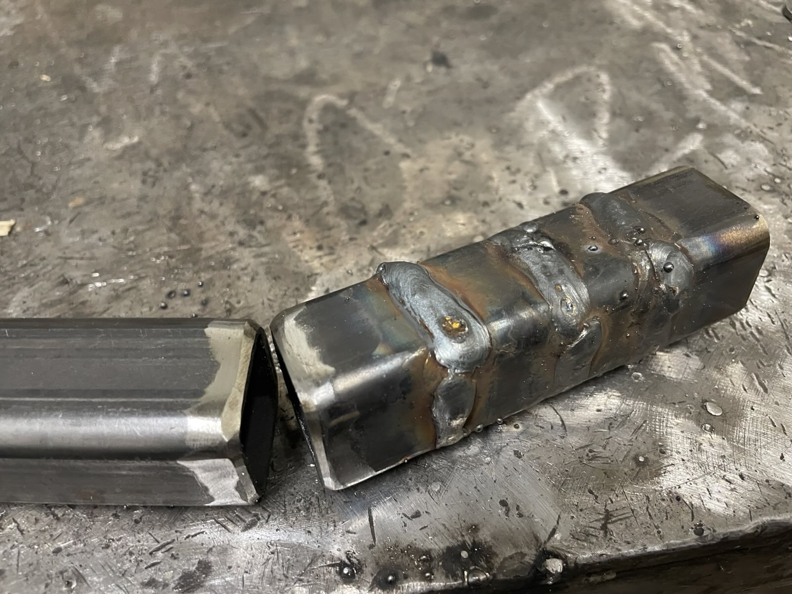
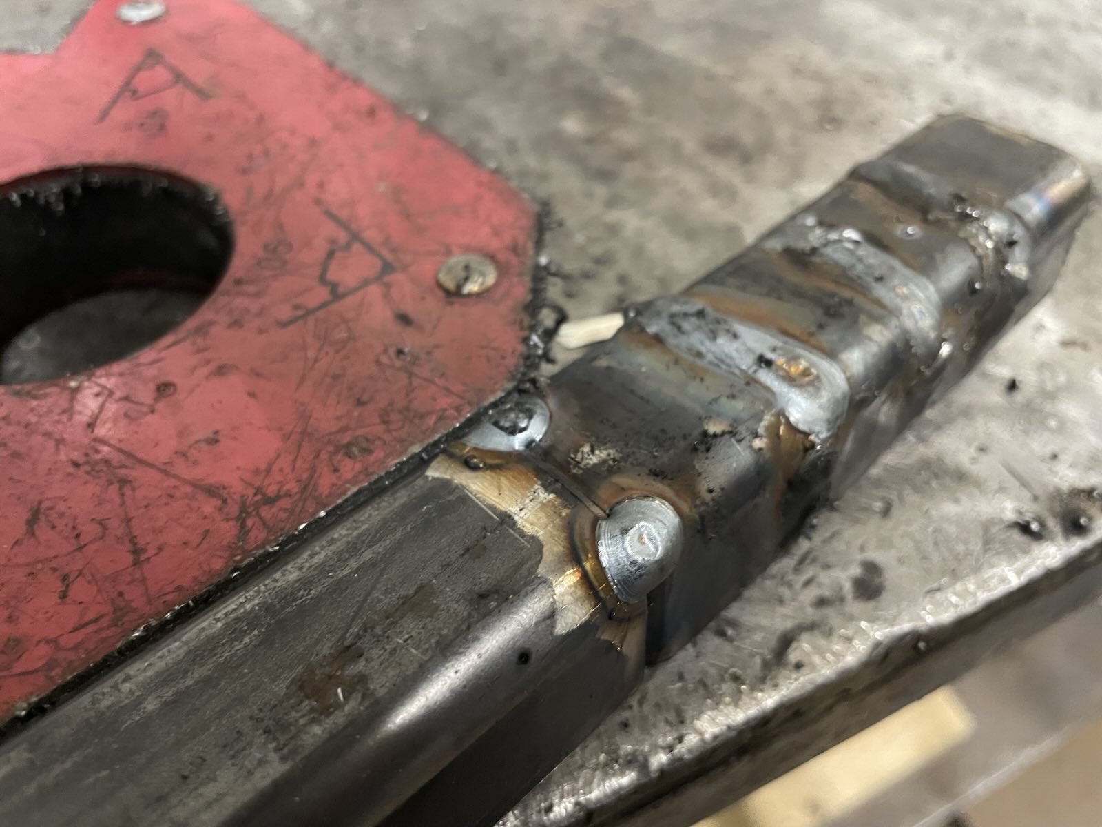
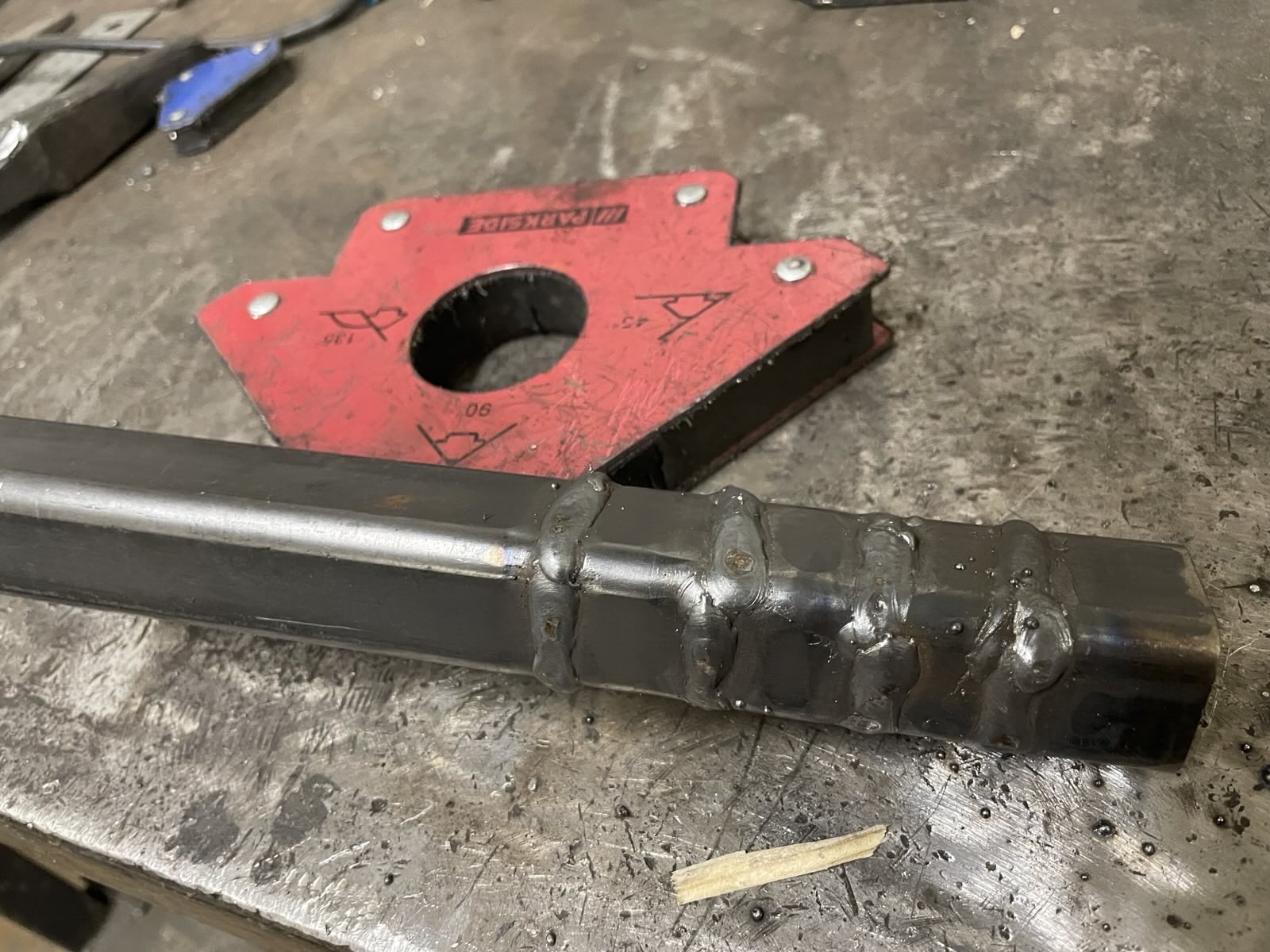
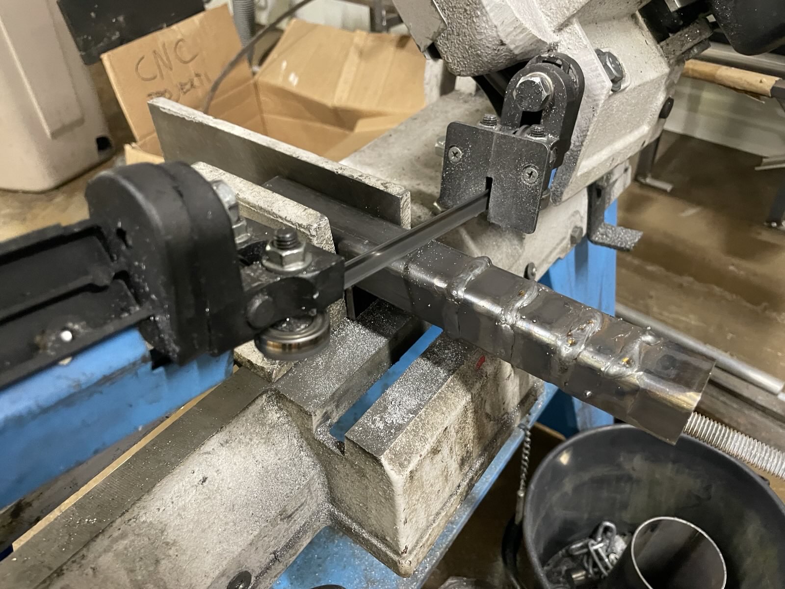
The original pushrod is just about the right length too, but it needs an adapter made.
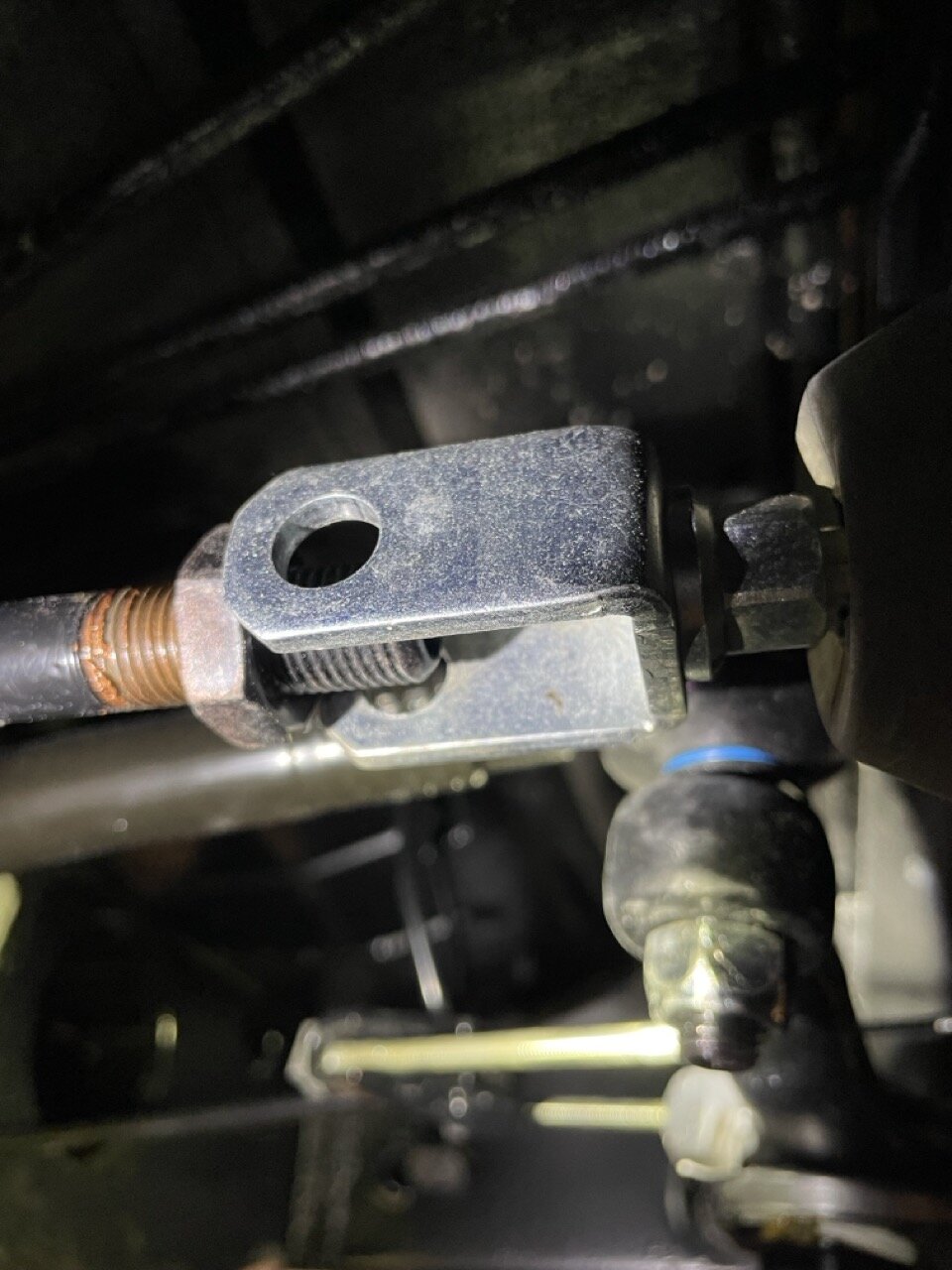
I tried to an uniball to the yoke - terrible idea in afterthought as it bends from too many places! Needs to have a rigid piece connecting the two. The thread on the VW original is M14x1.5 and the booster has M8 on the receiving end. Just a small cylindrical piece with tapped threads should work, but our lathe gave up just when I discovered this. So I'm not waiting to get that fixed first.
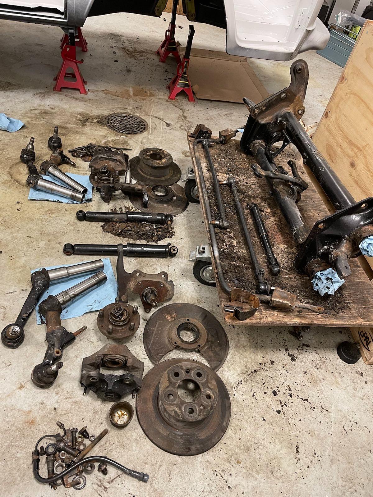
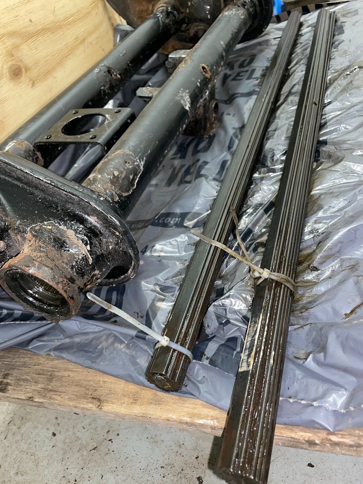
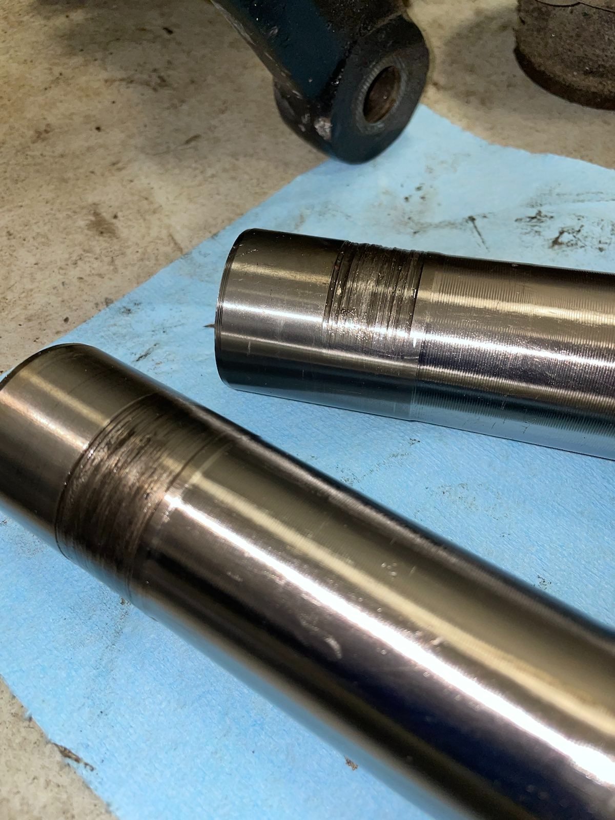
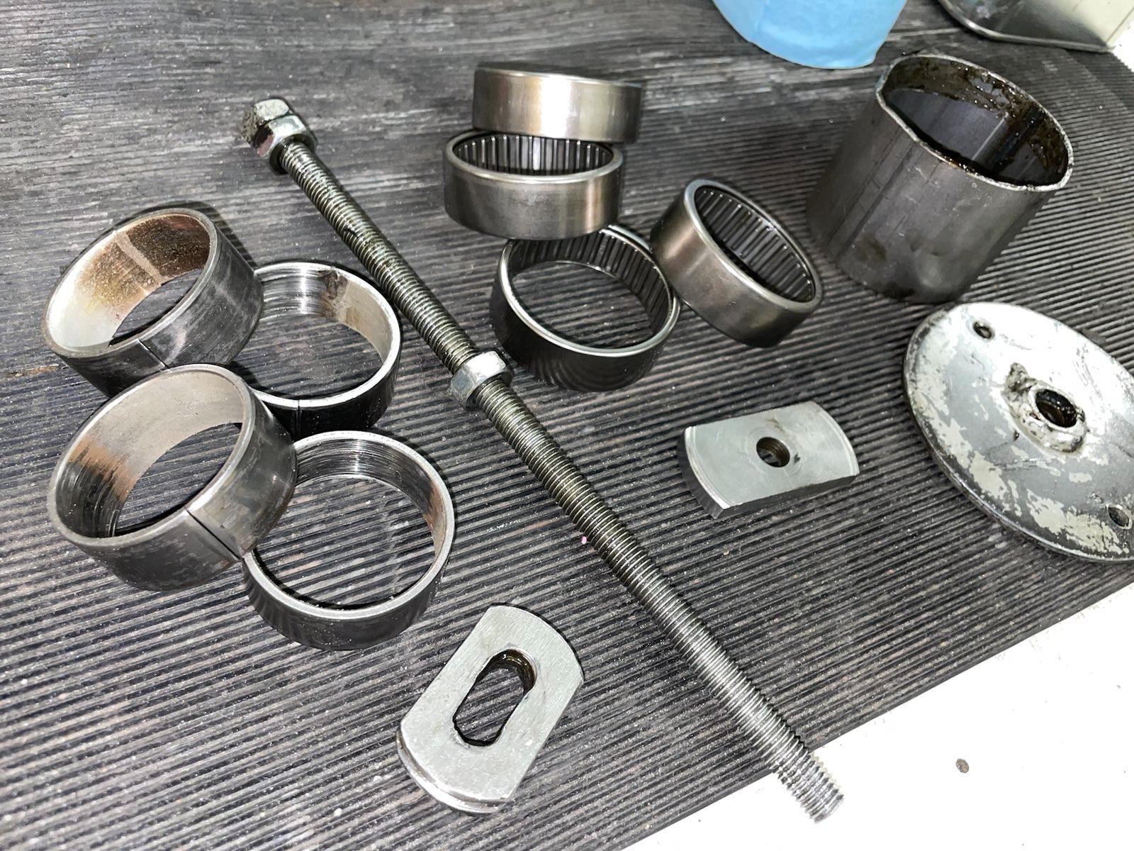
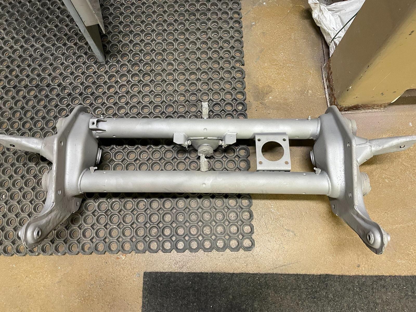
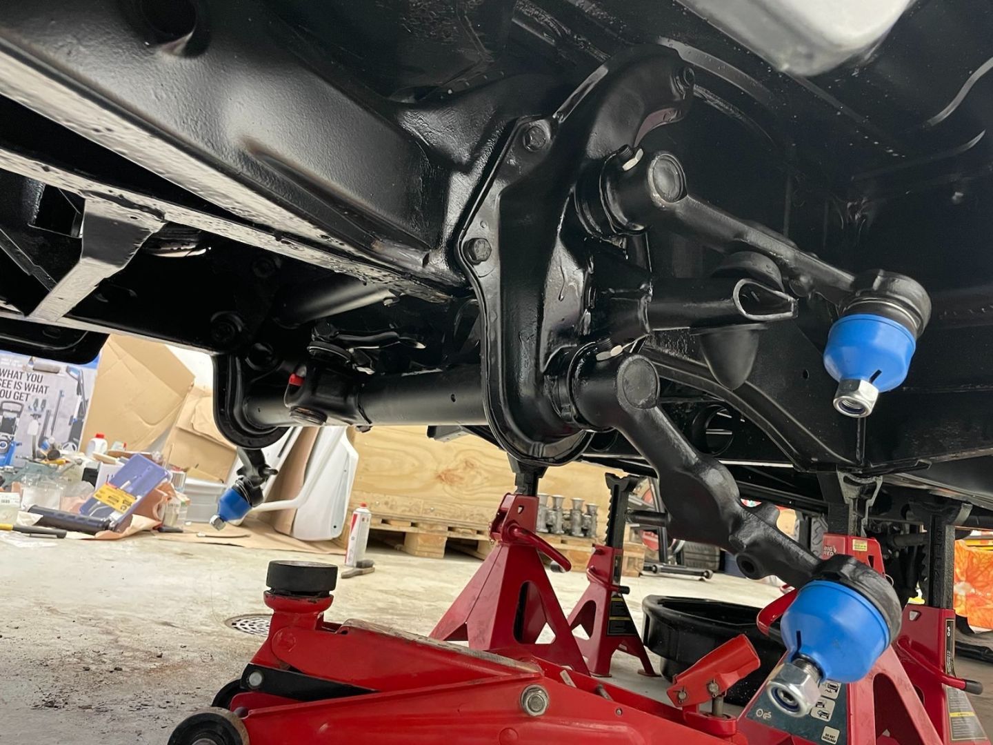
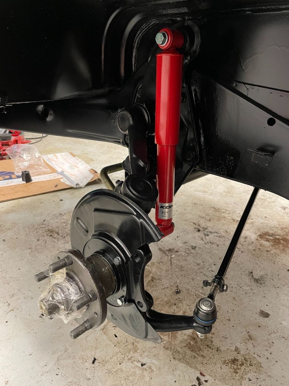
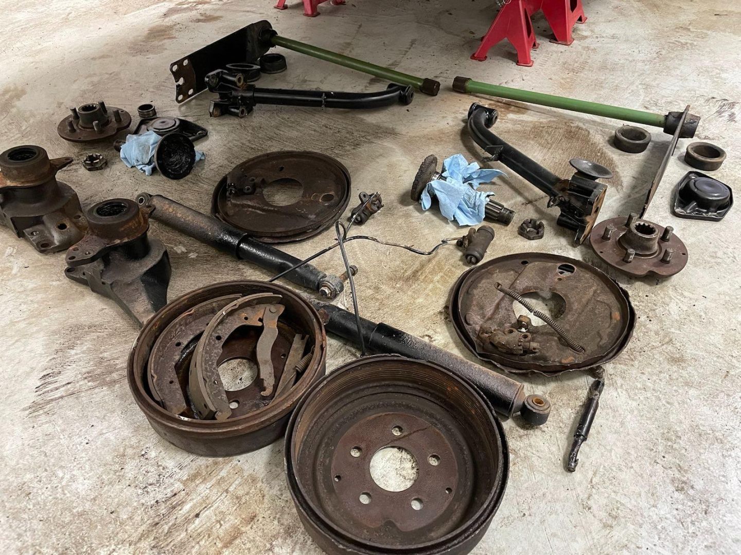
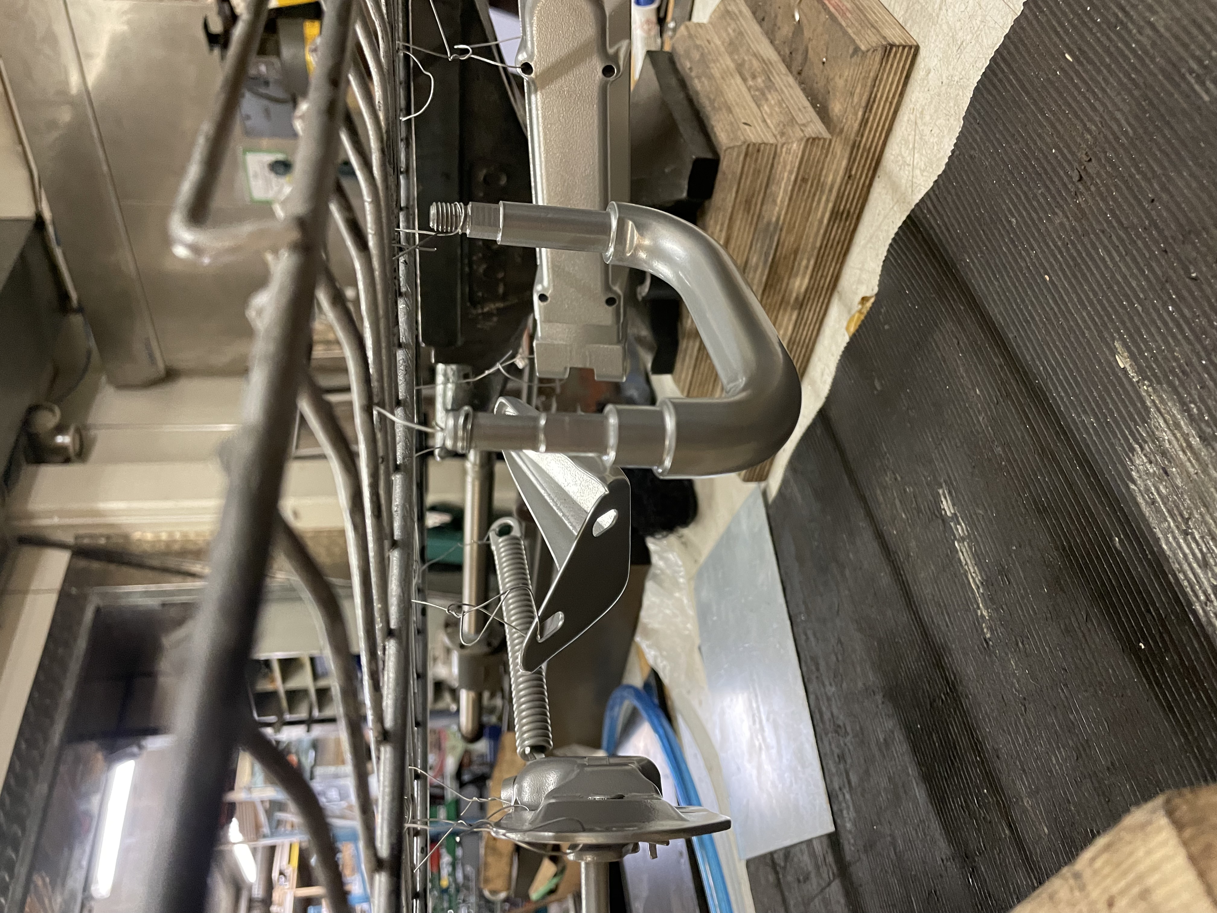
I also restored the original CV axles:
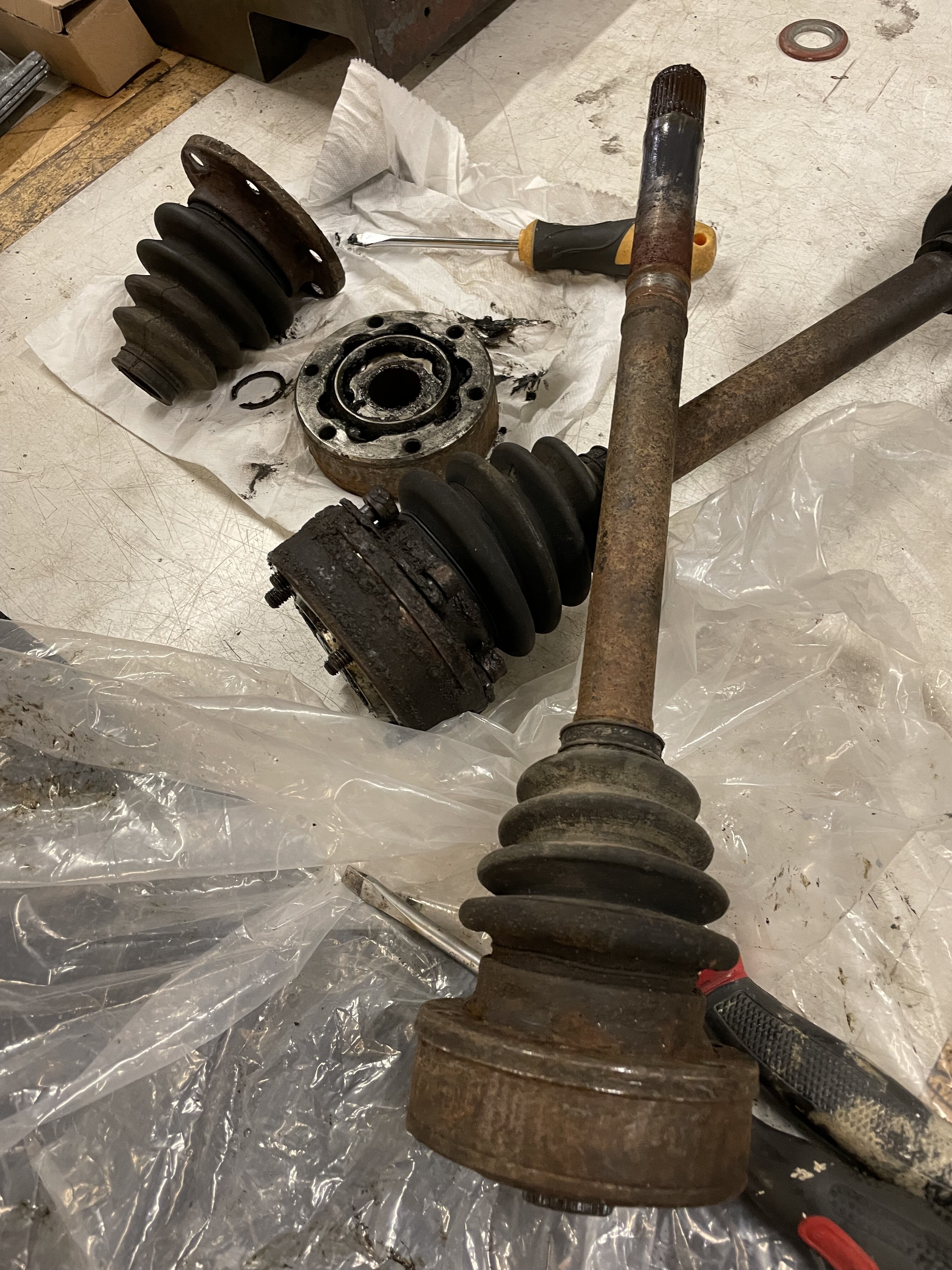
Joints were stamped 1975, some of them did look like it too
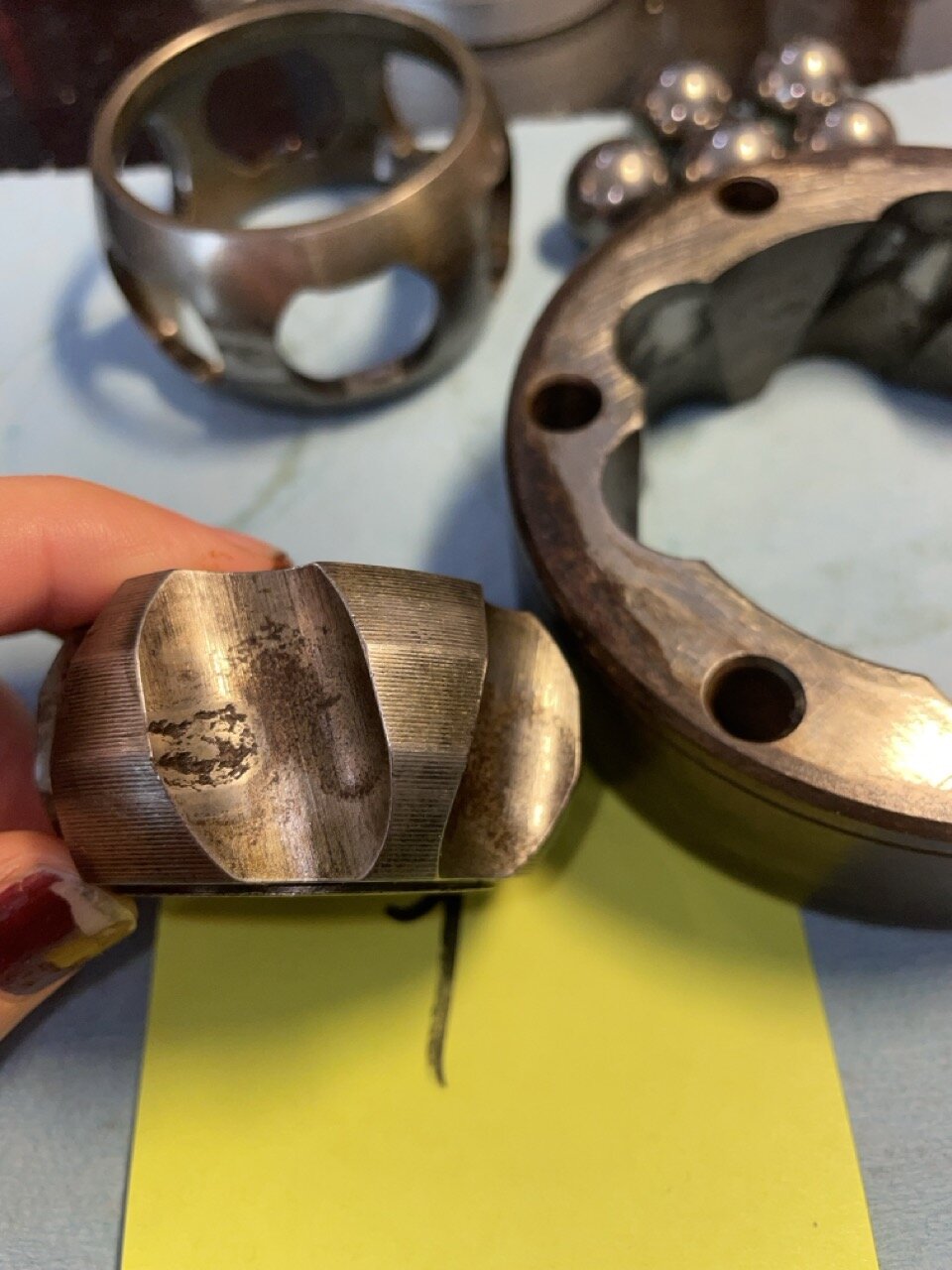
In the end I replaced two of the joints which had worn the worst and kept the two better ones.
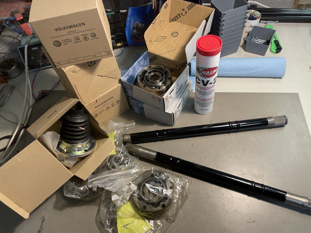
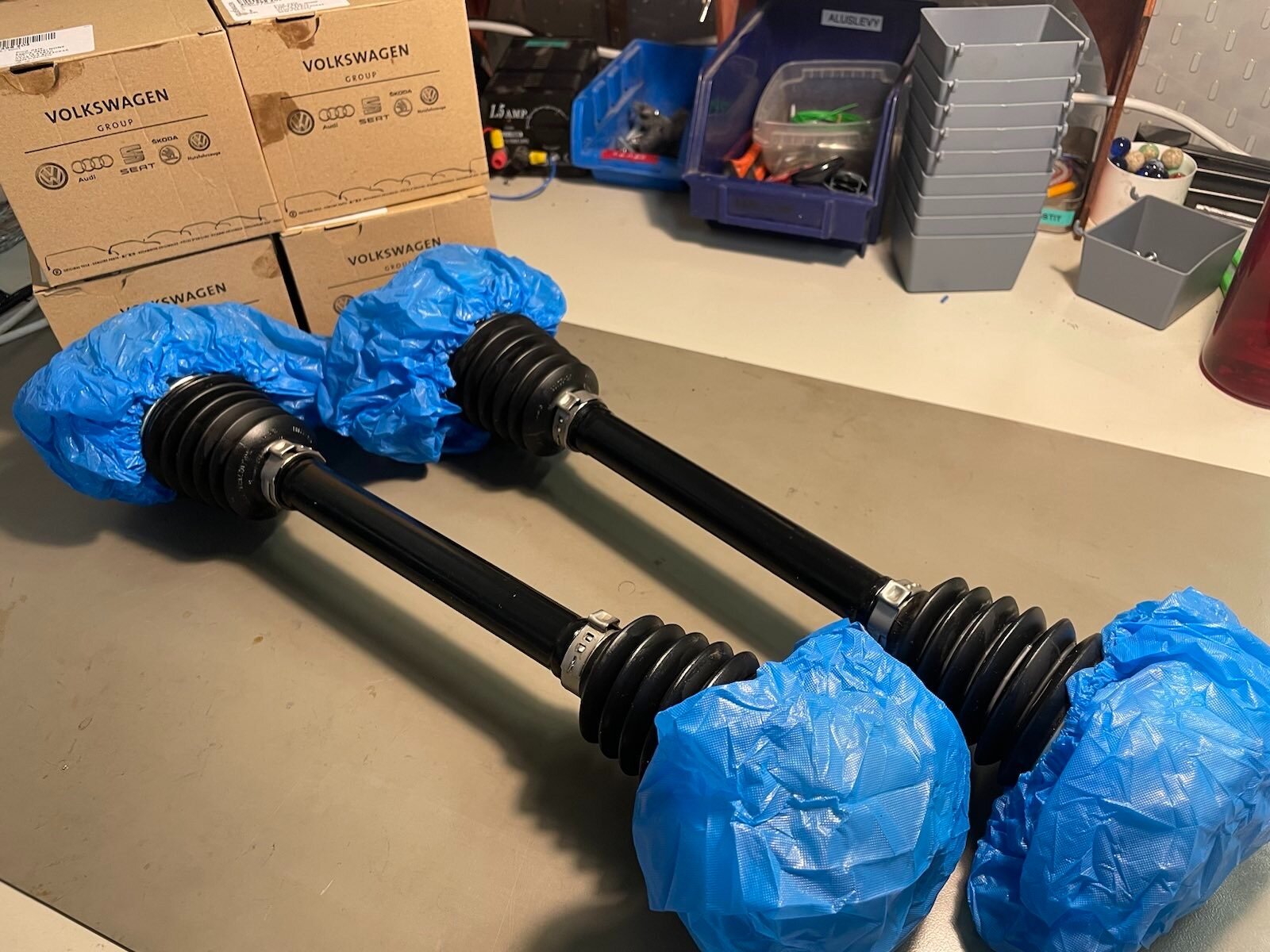
Liberal amounts of grease, new VW rubber boots, powder coated the axles and it's like they never left the factory!
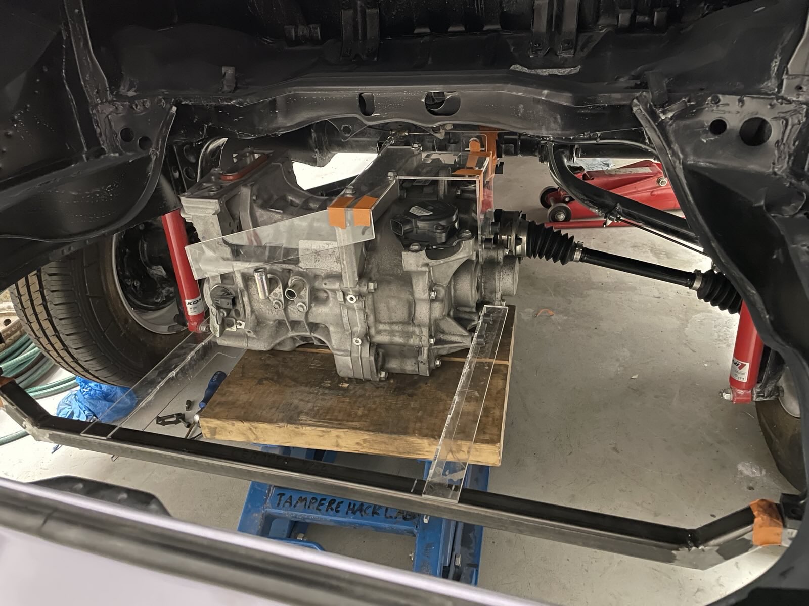
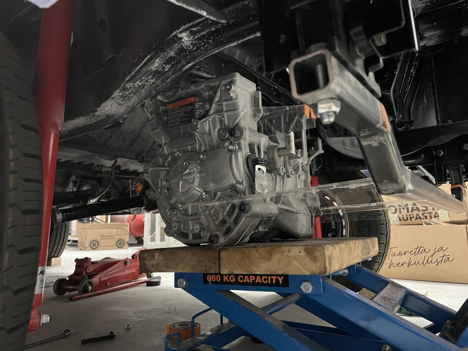
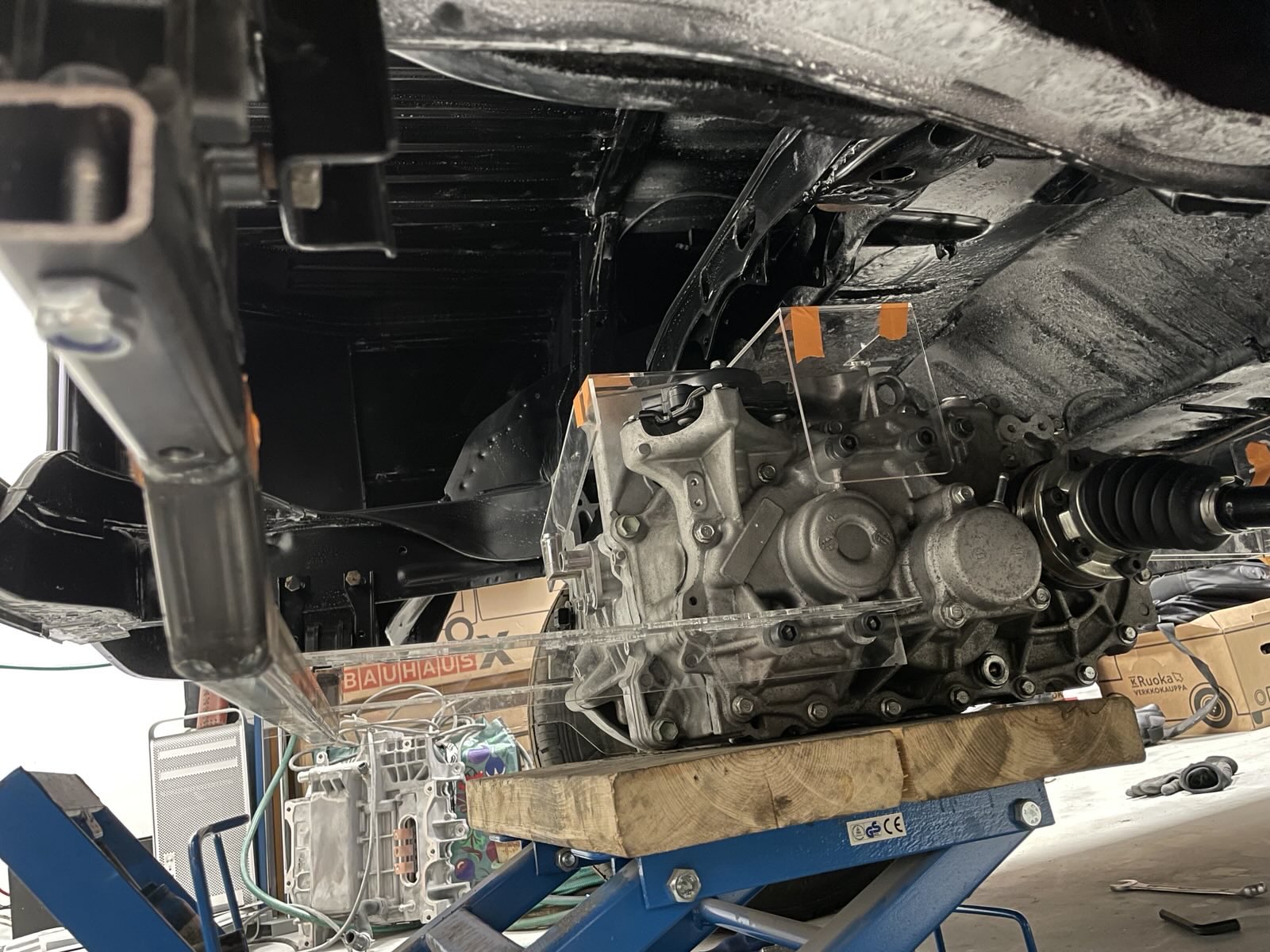
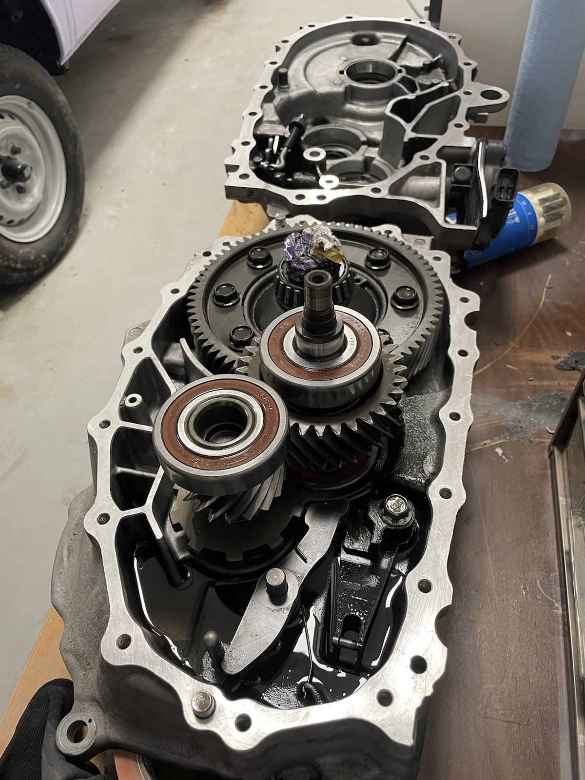
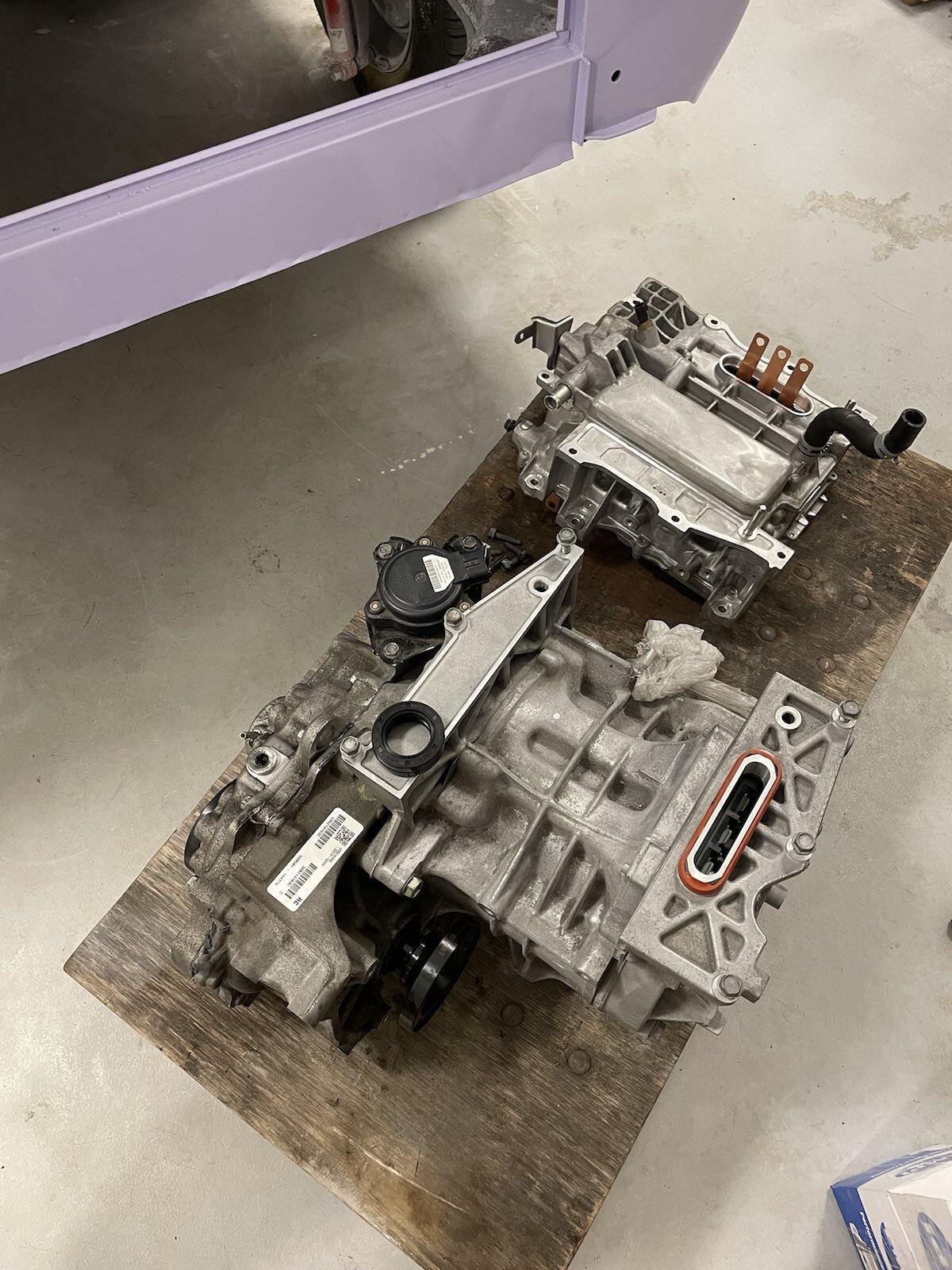
I also reassembled the Leaf gearbox. I ended up not designing any alternative lubrication for running this in reverse. There's been multiple reports on people using these care-free in reverse as long as they've had the shielded bearings and preferably bit overfilled with oil so I'm just going to risk it, too.
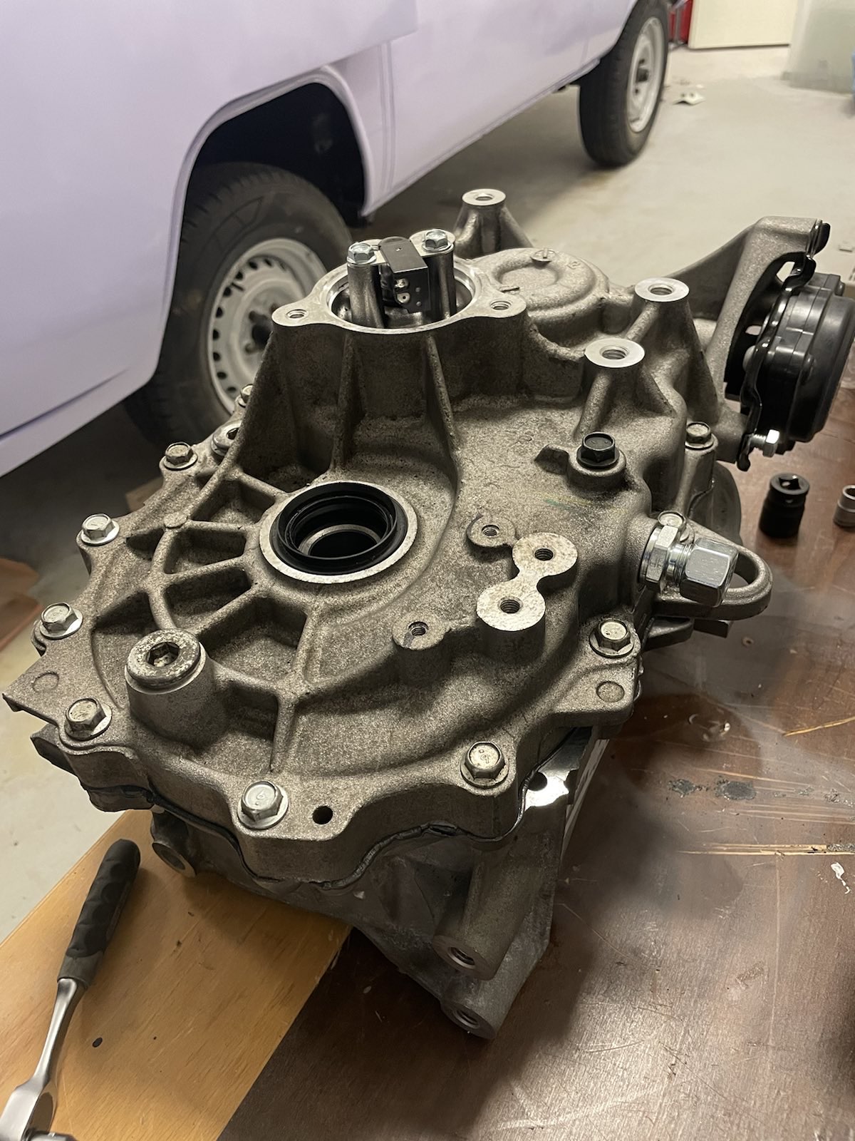
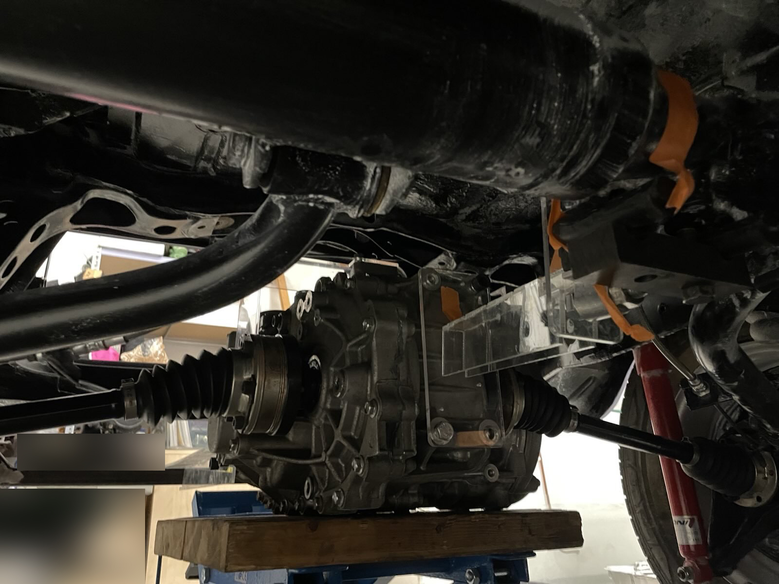
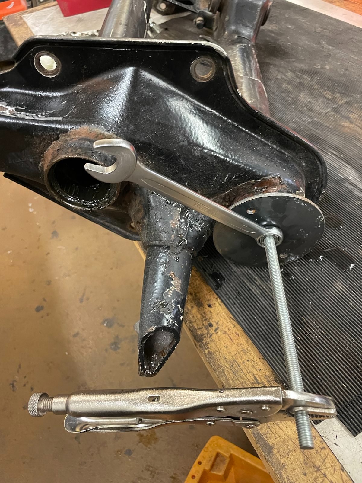
Which means that the stubs from bratindustries and drive flanges can be mounted, too.
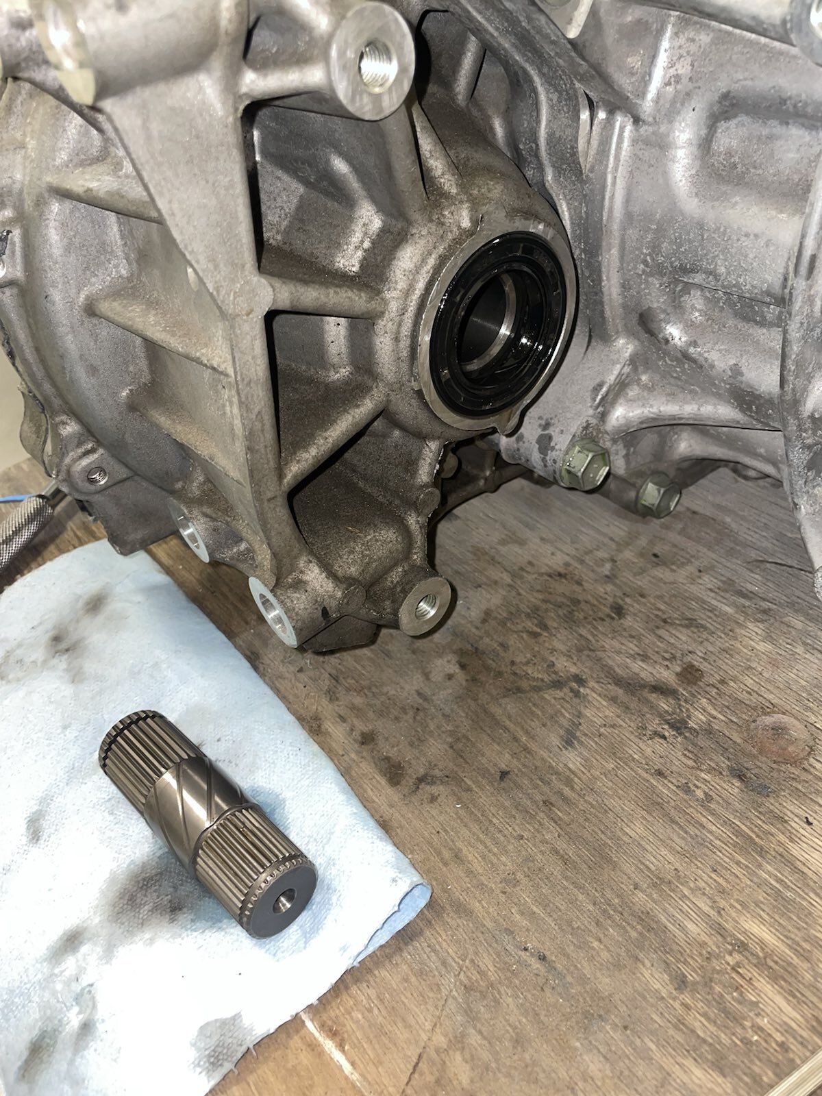
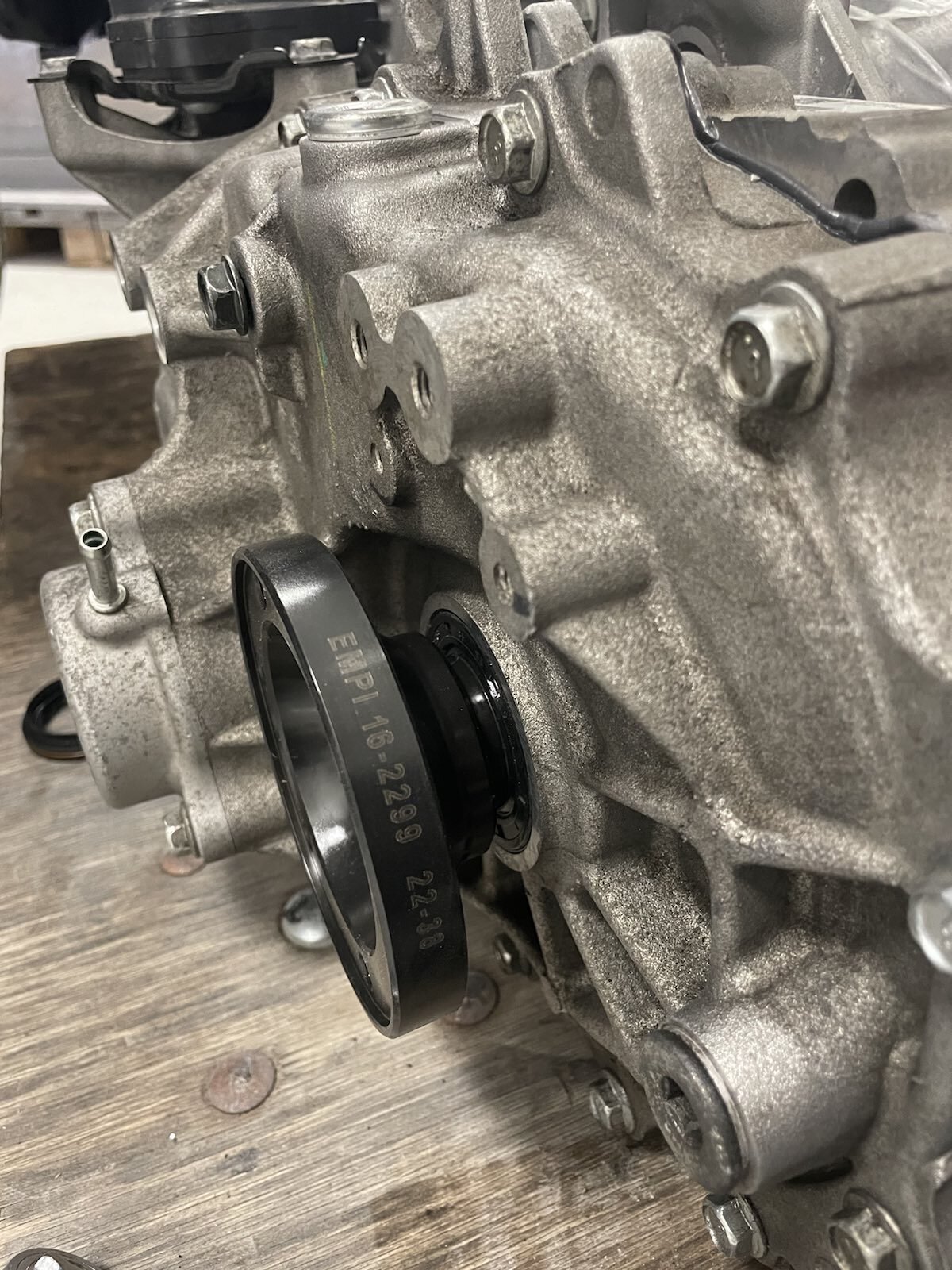
Fits perfectly.
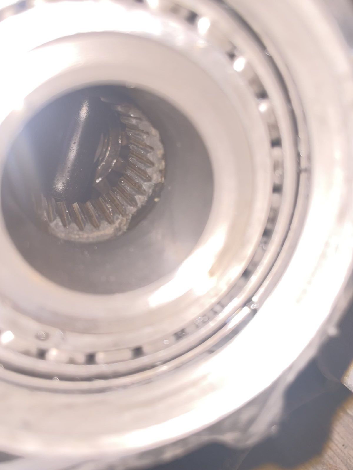
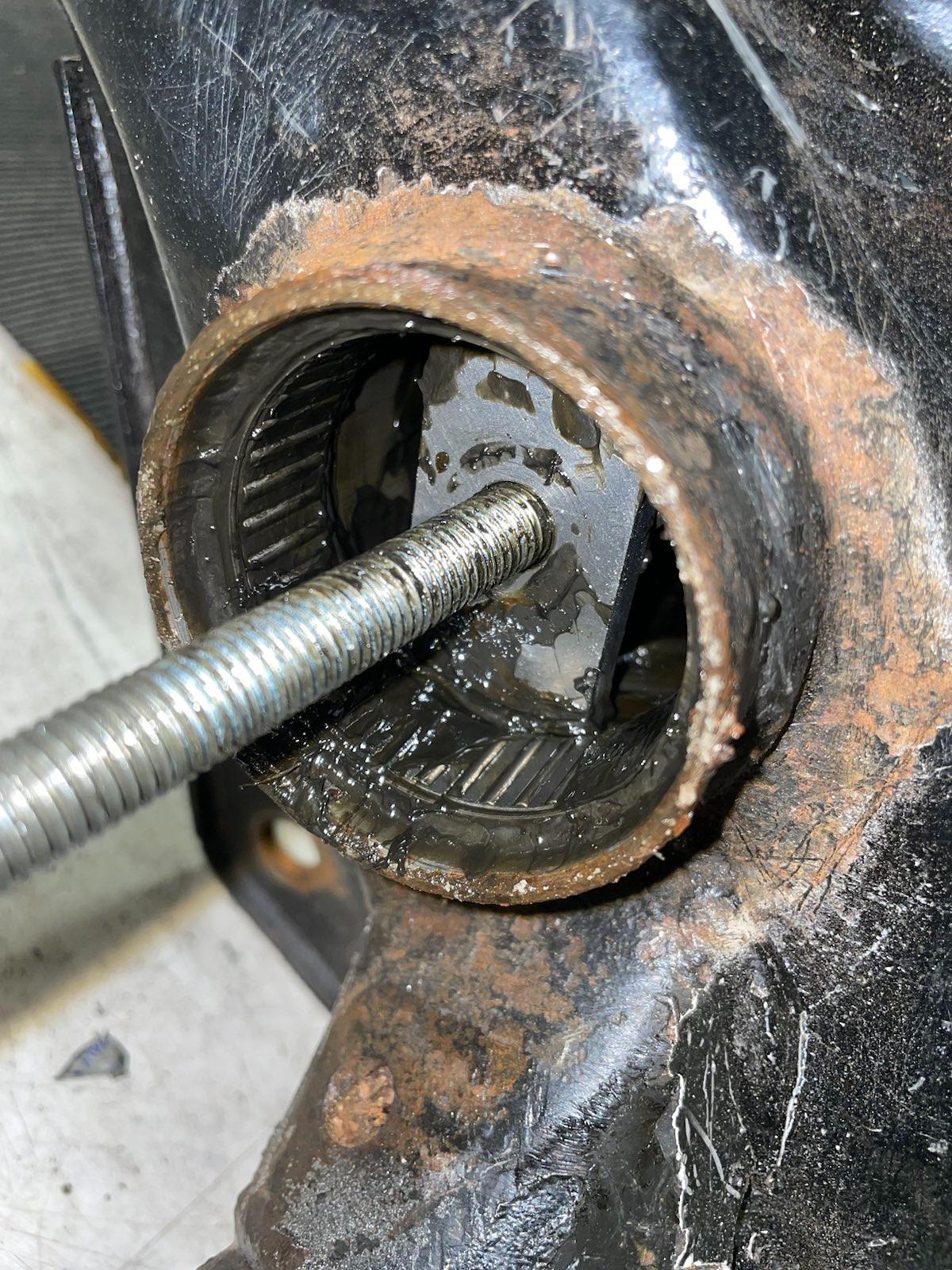
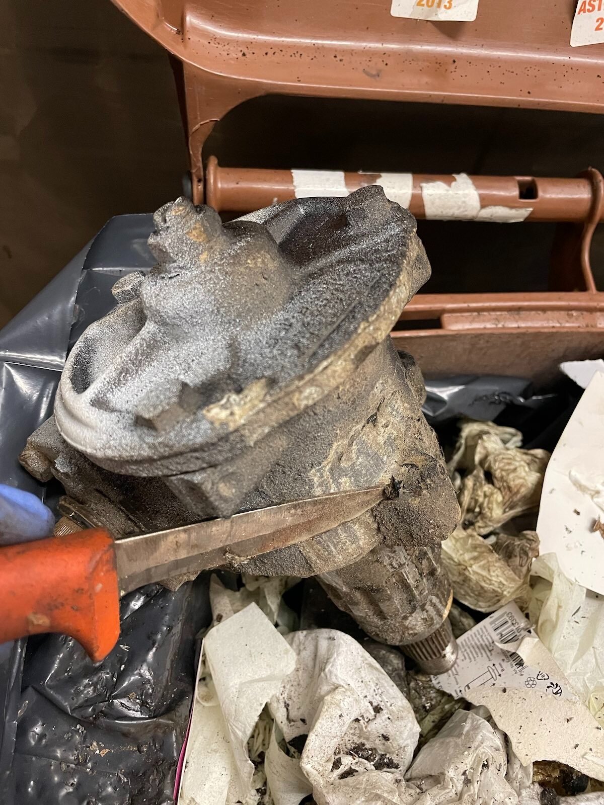
I also noticed, at this point only, that this gearbox which I bought with the motor has some damage on the differential gear outer face. I never removed the largest helical while disassembling this, so I only saw it now when changing the oil seals for the stub axles.
There's pretty large chunks of metal missing from the outer edge of the gear.

I eventually found these larger chunks from the magnetic plug below the largest helical.
Video:
https://ceravyn.net/up/VW/IMG_4247.mp4
I'm not undoing the sealant glue I just put into place before noticing this, nor do I have any replacement gears or anything to fix this, so I'll leave that be. I also think this isn't going to be any problem for me, as it looks that the damage is on the outermost edge only, which I figure doesn't have any real forces applied to it so I'm confused how this has even happened.

Current leading theory is that maybe the car this was disassembled from had some sort of collision which briefly pushed the driveshaft on this side inwards too much, splines ran out and something contacted the gear face? I don't know.
Anyway. Moving on.
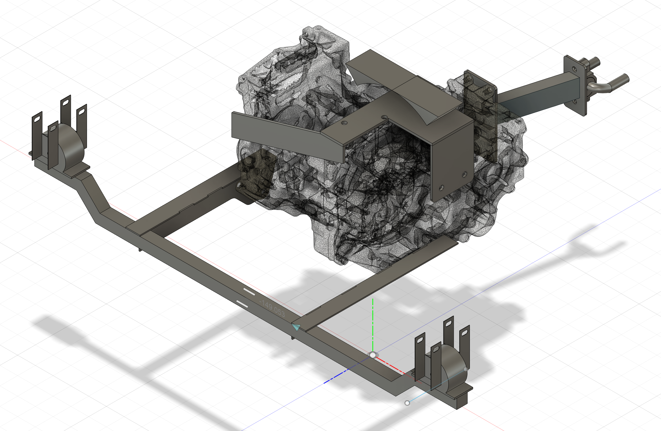
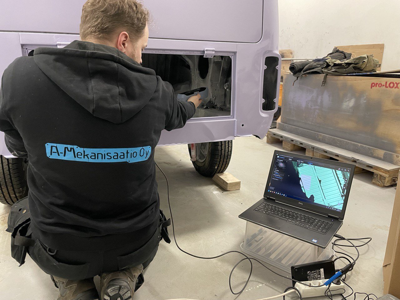
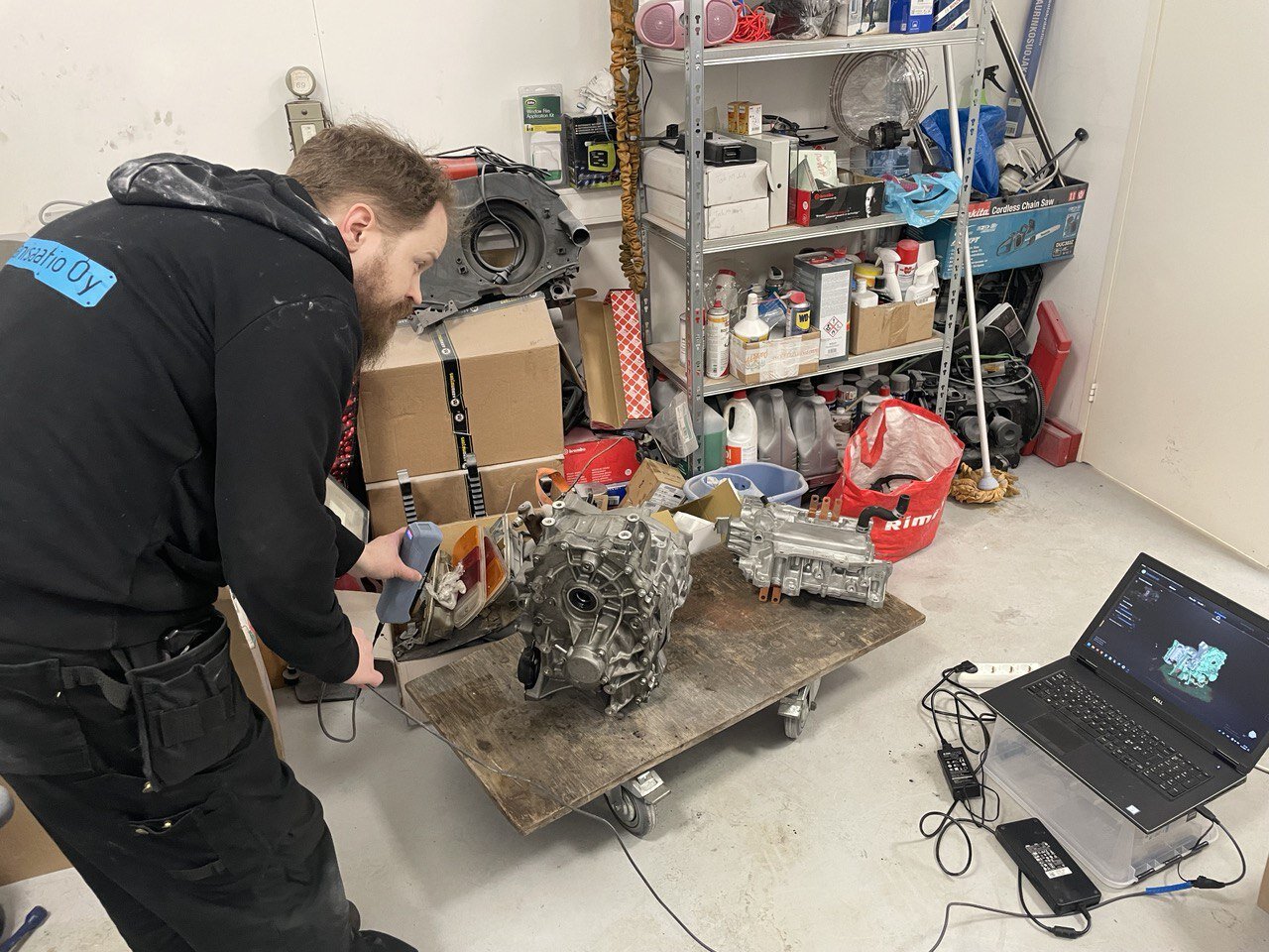
We 3D scanned the whole engin... I mean motor bay.
https://volkkaripalsta.com/keskustelu/u ... a4dc15.mp4
Thanks to Arno from local hackerspace (and his company
https://mekanisaatio.fi )
And the Leaf motor, although that probably would've been available.
Phew. Hows that for an update?
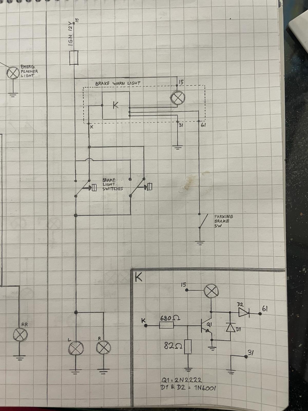
On the drawing board now, whole 12V electrics:
And plans for how to mount the batteries:
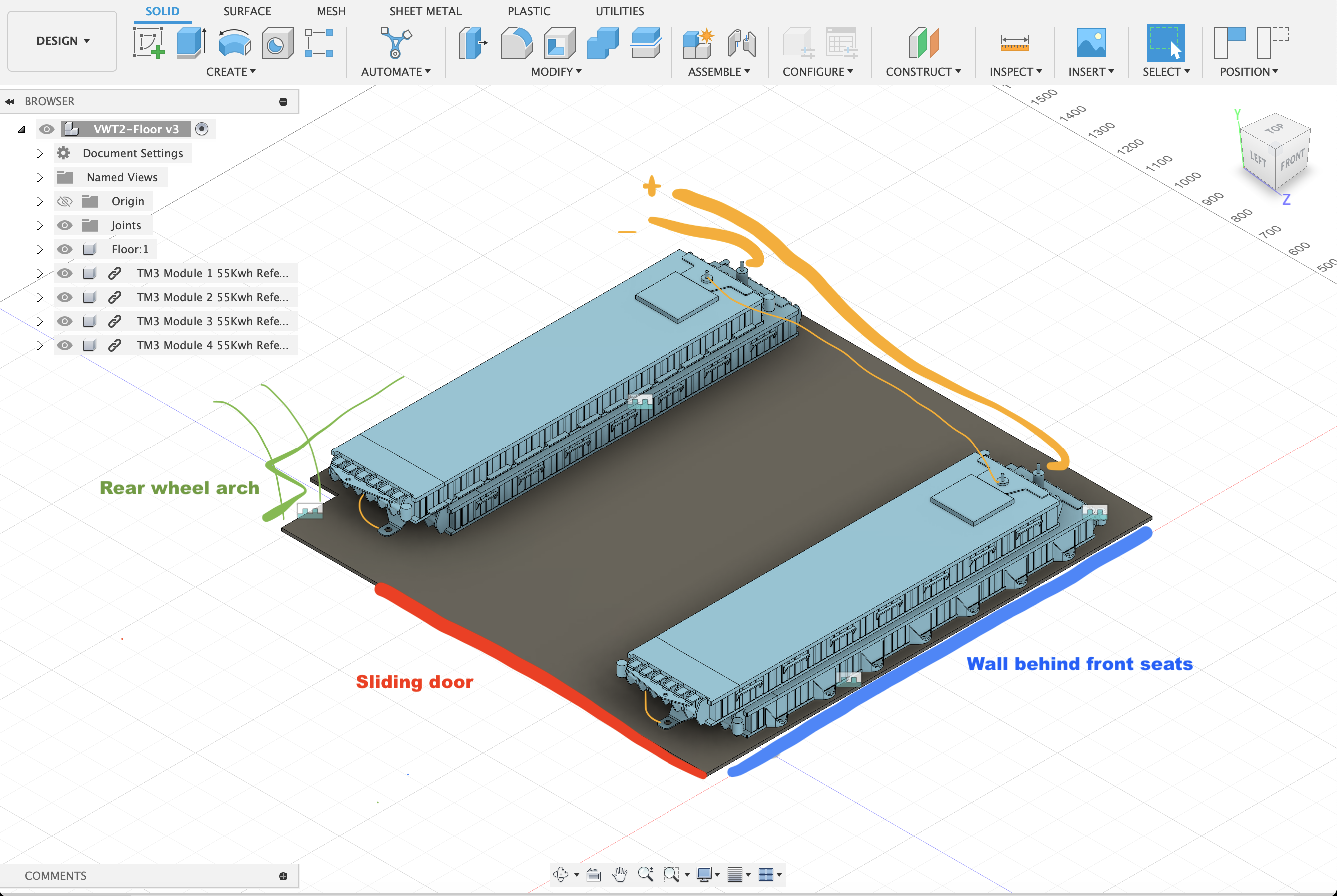
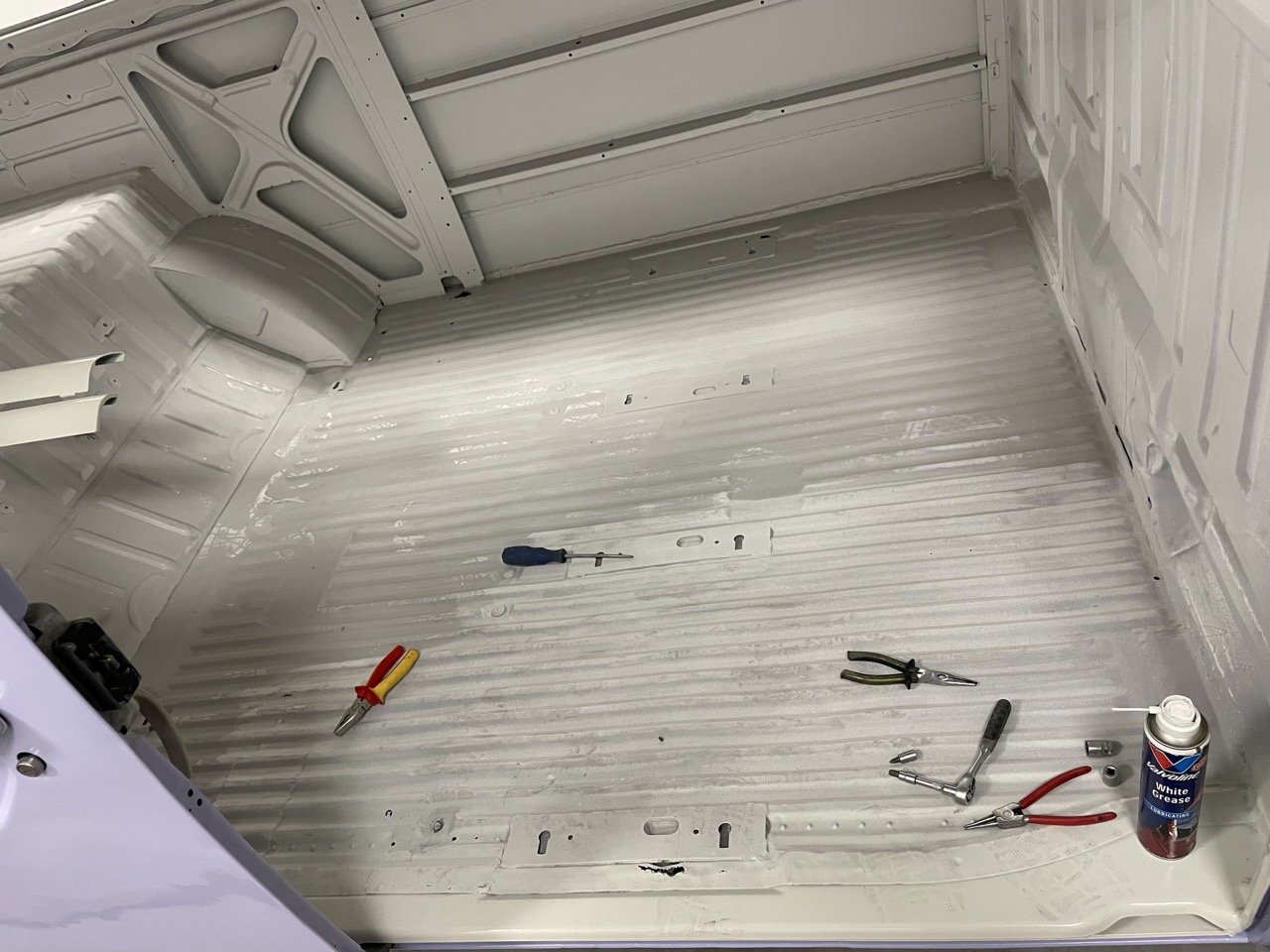
Cargo space for context:


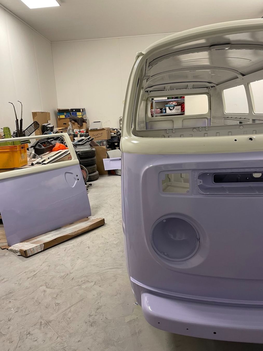
 Now it looks like a proper car!