Page 6 of 12
Re: Kia Niro BMS
Posted: Sun Nov 05, 2023 4:44 pm
by manny
haven't looked at that bit. The attiny is not on the board jet.
but the compareVoltage should not be higher than the batteryVoltage maybe eaquel. Maybe add a percentage.
the 300V can be calculated from minimum cell voltage and number of cells.
yes there is contactor control on the pcb. I added a extra channel. so pre charge main positive and main negative.
changing the code for one channel current sensor is easy.
using the voltage measurement from the inverter is a neat idea.
Re: Kia Niro BMS
Posted: Sun Nov 05, 2023 5:03 pm
by bexander
manny wrote: ↑Sun Nov 05, 2023 12:04 pm
Got it working with my modules (3 at the moment).
Not sure that i got all the hard coded bits.
The split in cell layout in the original code is hard to code for, so I removed it
Code: Select all
void storeCellVoltage(uint8_t dataRegister, uint8_t readRegisterData[29])
and
Code: Select all
void storeCellTemperature(uint8_t readRegisterData[29])
They are limited to input of 29 bytes. Should be changed to "message length" I guess?
Re: Kia Niro BMS
Posted: Sun Nov 05, 2023 5:12 pm
by bigmotherwhale
Did you also implement PWM for economiser control of your contactors? you mind sharing your code for this?
it may be easy for you, programming is not something I find easy.
I have tried modifying the code to use an extra pin for the contactor and analogwrite with a delay going from value 255 then 50, have removed the low current sensor part of the code as best i could see, will have to tweak the scaling when I work out what the sensor range actually is.
Re: Kia Niro BMS
Posted: Tue Nov 07, 2023 10:58 pm
by bigmotherwhale
The lack of a datasheet for the contactors is problematic. Doing some testing has left me wondering whether the contactors need PWM after all, it seems the hold off setting needs to be a lot higher than i have seen with other contactors.
The contactors are driven from a BTS723GW on the existing PCB, I have seen very little in the datasheet or elsewhere on this being used for PWM. Could anyone tell me if this is likely to be used like this?
This is my current code with the added extra contactor which just enables after powerup, and PWM control at 10khz using timer 1 on pins 9 and 10.
It seems that there is no hard high and low cut off in the existing code?
Re: Kia Niro BMS
Posted: Wed Nov 08, 2023 12:40 pm
by bexander
bigmotherwhale wrote: ↑Tue Nov 07, 2023 10:58 pm
It seems that there is no hard high and low cut off in the existing code?
That is correct, it only triggers warnings. Hard cut offs has to be done by the driver.
Re: Kia Niro BMS
Posted: Fri Nov 10, 2023 2:43 pm
by bigmotherwhale
Im trying to get the thermistor value into the existing cellblock temp in the code but i don't know where to call for it,
I got it to read and serial print data in the loop so i know its working but I want to make use of the high and low cell functions to put in some hardware protections for high and low temperature, could you have a look at this code? Thanks
Re: Kia Niro BMS
Posted: Fri Nov 10, 2023 4:20 pm
by bexander
I guess you could put the call to the "storeCellTemperature()" inside the 250ms function in the main loop, i.e after the "measureCellData();" call.
If you only have two thermistors you could use the MIN and MAX arduino functions.
Re: Kia Niro BMS
Posted: Sat Nov 11, 2023 10:52 pm
by bigmotherwhale
That worked well, the thermistor value is populated in the place that it should, but with extra 0 readings that i need to remove.
Im having trouble with the contactors, your code originally read the precharge pin directly but as i am now using pwmWrite thats not possible so i changed that to checkvoltage.
Im also just using analogue read to determine inverter voltage at the moment and something isnt right, i had to remove the newdata part and now i get spammed with the analogue reading and then get "contactor error message"
Re: Kia Niro BMS
Posted: Sun Nov 12, 2023 2:23 am
by bexander
Serch for "contactor error" in the code and try to figure out why this is triggered. Then work backwards from there.
Using analog read to determine inverter voltage? Are you measuring inverter voltage directly, without any kind of isolation interface?
Re: Kia Niro BMS
Posted: Sun Nov 12, 2023 2:40 am
by bigmotherwhale
Im currently using a resistor divider on the 5v line to emulate a voltage, the inverter has an ACPL-C87AT DC Voltage Isolation
Sensor onboard and i can use that or a can bus value it transmits from it.
Re: Kia Niro BMS
Posted: Wed Nov 15, 2023 12:10 pm
by AndrewM314
Hi,
I have been following this subject with interest for a while now as I am using Kia Niro/Hyundai Ioniq PHEV batteries for a solar energy storeage system(personal use), I have just built the BMS master following the drawings kindly shared by bexander(very much apreciated thanks).
unfortunately I don't appear to be receiving a reply back from the battery slaves.
firstly, do these Mobis slaves need powering by an external supply.
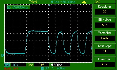
secondly, could someone please tell me if my transmission signal is ok or not.
i have attached screenshots of the transmission signal before and after the isolation transformer(CH1 is TXpositive, CH2 is TXnegative)
Re: Kia Niro BMS
Posted: Thu Nov 16, 2023 12:13 pm
by bexander
No external power neede other than the battery cells.
Are you using the OEM wires and all modules connected? How does your RX lines look in the scope?
Re: Kia Niro BMS
Posted: Thu Nov 16, 2023 6:00 pm
by AndrewM314
bexander wrote: ↑Thu Nov 16, 2023 12:13 pm
No external power neede other than the battery cells.
Are you using the OEM wires and all modules connected? How does your RX lines look in the scope?
Thanks for the reply, I found the main problem, I had the transmit from the master to transmit on the slave "Doh", I've corrected it and am now getting a signal on the RX lines.
Re: Kia Niro BMS
Posted: Fri Nov 17, 2023 3:47 pm
by marucha79
Do you know if 24,7Ah is total or netto capacity of this cells?
Re: Kia Niro BMS
Posted: Sat Nov 18, 2023 5:22 am
by bexander
I'm using 24,8Ah as the total capacity.
Re: Kia Niro BMS
Posted: Sun Nov 19, 2023 9:53 am
by marucha79
Could you tell about useable capacity when low limit is 3,2V per cell? In a fact I can test it by my charger, but when discharging relatively low current it won't be reliable. I think of buying battery for another project, but by budget about 1000 euros Outlander battery 12kWh seems to be better choice - more capacity and more configurable.
Re: Kia Niro BMS
Posted: Sun Nov 19, 2023 12:01 pm
by bexander
I only go down to 3,5V/cell and at that voltage I get approx 80% or 19,8Ah with summer conditions (~20degC in the battery).
Re: Kia Niro BMS
Posted: Sat Jan 27, 2024 12:26 pm
by Levin
Hi, Is there any way to test the small BMS-slave units with MAX17845 chips from a KIA/Hyundai 64kWh battery to check if they are working? I did have a look at your code "BMS2_7_3_EDITED_3_2.ino" @bexander but it contains a lot of code and functions as I understand. I have a battery with broken electronics but I hope some of the slave units is still working and I dont want to test them with a working BMU, I want to test them one by one with the cells connected, is it possible with some arduino board or oscilloscope?
Regards
Re: Kia Niro BMS
Posted: Tue Feb 20, 2024 5:07 am
by bexander
Levin wrote: ↑Sat Jan 27, 2024 12:26 pm
Hi, Is there any way to test the small BMS-slave units with MAX17845 chips from a KIA/Hyundai 64kWh battery to check if they are working? I did have a look at your code "BMS2_7_3_EDITED_3_2.ino" @bexander but it contains a lot of code and functions as I understand. I have a battery with broken electronics but I hope some of the slave units is still working and I dont want to test them with a working BMU, I want to test them one by one with the cells connected, is it possible with some arduino board or oscilloscope?
Regards
These slave modules can be made to work in the same manner. The code need to be modified for the number of slave modules and at what positions the cells are connected.
Note, the slaves contain 2 pcs of MAX17845 an can therefore handle 24 cells each.
I think the information on what needs to be changed can be found in this thread with some detective work.
Re: Kia Niro BMS
Posted: Tue Feb 20, 2024 9:20 am
by maarek2
Dear Bexander
I have some problems with balancing (with your original code).
After Balancing ON cell current coming from cell to BMS (+70mA / 20second / good condition) but after this current coming from BMS to cell (-70mA 20second). These both directions are in the loop.
Could you please check if you have same condition in your BMS.
In my opinion only current coming from cell to BMS is OK for ballance.
Thank you
Marek
Re: Kia Niro BMS
Posted: Tue Feb 20, 2024 3:51 pm
by bexander
maarek2 wrote: ↑Tue Feb 20, 2024 9:20 am
After Balancing ON cell current coming from cell to BMS (+70mA / 20second / good condition) but after this current coming from BMS to cell (-70mA 20second). These both directions are in the loop.
This is normal and expected behavior.
The slave chip (MAX17823) can not handle balancing adjecent cells simultaneously so in the code I do all odd cells first for a period and then switches to all even cells for a period.
Example using only cell 1 and 2.
During first period all odd cells (cell 1) is discharged and the current is flowing according to green line and arrows. During second period all even cells (cell 2) is discharged and the current is flowing according to blue line and arrows. This results in the behavoir you are observing, that the measured current changes direction (sign) periodically when two adjecent cells are balanced.
 Viewed 18495 times")
- Balance current during different periods
Re: Kia Niro BMS
Posted: Tue Feb 20, 2024 9:31 pm
by maarek2
Dear Bexander
Thank you very much for explanation. I found this part odd/even in * Balancing of cells * part.
Time depends on balanceCellCounterTurnAround.
Thank you again.
Marek
Re: Kia Niro BMS
Posted: Sun Jun 09, 2024 6:34 pm
by StephanL
Hi!
I was a "silent follower" since month, because we are converting a VW T2 to electric. Its nearly done - next week we want to go to the TÜV in Göttingen

One problem still has to be solved: The additional battery is using CATL Modules with the MAX BMS. I used the original CATL BMS Master and soldered some wires to it and it worked unstable, but it worked with my arduino and the kindly supplied code from the forum. After some time i couldnt get it to work anymore. Now i bought a new MAX 17841B Chip, just to be sure that it is not the problem. I also used a new Arduino.
On the original CATL-Master im still using the isolation Transformer. Its connectes via 0,5 mm2 wires.
I will attach some oszi prictures. Can somebody have a look at it?
My guess is, that the signal is too bad. It reaches the first BMS board and after that its not going to the next board. At the moment just two boards.
Thank you very much already for your help!
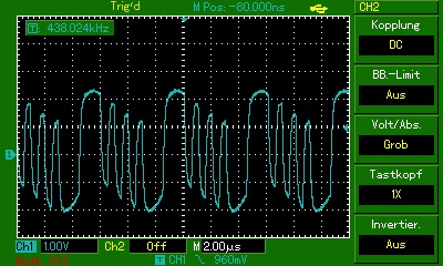
- Primary side of the transformer.jpg (56.42 KiB) Viewed 14379 times
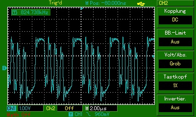
- Secondary side of the transformer.jpg (58.61 KiB) Viewed 14379 times
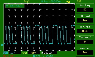
- output of the MAX BMS Master Chip to ground.jpg (55.81 KiB) Viewed 14379 times
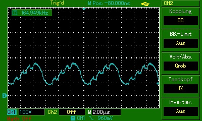
- another primary side of the transformer to ground.jpg (52.53 KiB) Viewed 14379 times
- one primary side of the transformer to ground.jpg (52.33 KiB) Viewed 14379 times
Re: Kia Niro BMS
Posted: Sun Jun 09, 2024 7:28 pm
by johu
Welcome
Can't help you on the subject but now that your first post is approved you can attach pictures
Re: Kia Niro BMS
Posted: Mon Jun 10, 2024 4:18 am
by bexander
What is the bandwidth of your oscilloscope? The base frequency of the signal is 2MHz and a low oscilloscope bandwidth will explain the rounded corners of the signals.
Measuring on the secondary side to ground means you are at the same time shorting out the isolation that the transformer is to provide. This way you might pick up a lot of interference. The signals are differential signal so should be better to measure them differentaly, especially on the secondary side. Measure SEC2_3 referenced to SEC2_1 and SEC1_3 referenced to SEC1_1.
 Viewed 14354 times")
- MAX17841 schematic
However I would not suspect the signal as the first source of error.
What is the response from the code when trying to run it on the Arduino? Where does it fail?