Using a PMSM and inverter to generate and regulate a DC voltage
-
uhi22

- Posts: 1244
- Joined: Mon Mar 14, 2022 3:20 pm
- Location: Ingolstadt/Germany
- Has thanked: 245 times
- Been thanked: 684 times
Re: Using a PMSM and inverter to generate and regulate a DC voltage
To avoid bricking the inverters, the idea with the Zener diode is good. Something which clamps the voltage at let's say 450V. But this sounds easier than it actually is. Because: The inverter tries to drive a current of let's say 10A or 100A or even more. The voltage during clamping is let's say 450V. So the "Zener diode" needs to dissipate P = U*I = 4.5kW or 45kW or even more into heat. So this "Zener diode" could be constructed out of 1000 pieces of FETs on a big aluminium wall, each of it capable of burning 50W. Just to give an impression about the size.
Github: http://github.com/uhi22 --- Patreon: https://www.patreon.com/uhi22
-
jrbe
- Posts: 766
- Joined: Mon Jul 03, 2023 3:17 pm
- Location: CT, central shoreline, USA
- Has thanked: 360 times
- Been thanked: 249 times
Re: Using a PMSM and inverter to generate and regulate a DC voltage
Zeners are fast but fail shorted when pushed past their limit. A gas discharge tube can handle much more power but are slow. You could use a higher voltage Zener and a gas discharge tube at a lower voltage so the Zener acts fast then hands the effort over to the gas discharge tube. But again, zeners fail shorted or fail exploded.
MOVs are a middle ground both on speed and strength. They fail exploded or cracked.
Using overvoltage to trigger a load dump resistor is a good idea but be sure it can handle the power. I'd look at using an overvoltage trigger to connect the load trying to keep the Zener out of the high power side of the circuit. Tricky bit will be how quick it can turn on.
TVS is a Zener meant to handle more power. And realize when this kicks in the heating is intense, it's very easy to blow. A resistor inline will have voltage drop, need to consider this. It's resistance will likely change with temperature too depending on how hot it gets.
Re: Using a PMSM and inverter to generate and regulate a DC voltage
The current idea for a zenode diode circuit is to use the diode(s) to divert current to a resistor bank when voltage exceeds 400V. Thinking of using 240V water heater elements wired in series to accomplish that, at least for testing purposes.
Back to the discussion of regulation, though: is it far fetched to replace the current sensing with voltage sensing instead? Is current sensing absolutely required?
Okay, we've learned a lot more now about how this works. We'll be more careful on the next go, and probably no more trial runs without the zener diode circuit.johu wrote: ↑Wed Feb 04, 2026 8:18 am No load on DC bus, requested current not reached -> "infinite" voltage
Yes. And have a load.
I think this only has a chance if you go "load first". So request torque from the motor, then bring on regen from the generator. Stop regen on generator, stop requesting torque. And even then it will be brittle.
Back to the discussion of regulation, though: is it far fetched to replace the current sensing with voltage sensing instead? Is current sensing absolutely required?
-
johu

- Site Admin
- Posts: 7182
- Joined: Thu Nov 08, 2018 10:52 pm
- Location: Kassel/Germany
- Has thanked: 552 times
- Been thanked: 1913 times
- Contact:
Re: Using a PMSM and inverter to generate and regulate a DC voltage
Yes current sensing is crucial for motor control. Like said, there is a voltage regulator already built in (udcmax). But the Leaf inverter encodes the voltage with a 500 Hz PWM which already limits bandwidth and then the OI board adds more low pass filtering to recover an analog voltage eating more bandwidth. And then software adds more low pass filtering. Like said, this was never meant to run without a battery and a battery has a huuuge time constant.
Now you can of course implement your own DC voltage sensing and deliver that to the OI board. You can also play with the HW and SW low pass filters and make them quicker. And on top of that you could try to implement fast transient detection that instantly shuts down PWM via the desat input on over voltage.
Ok, all that for a bit of tractor pulling... perhaps a revving smell-engine + 3-phase rectifier would suffice. Can't take advantage of reluctance torque that way though, so only perhaps half the power output.
Or change that regulation to allow a god damn battery.
Whichever seems easier
Support R/D and forum on Patreon: https://patreon.com/openinverter - Subscribe on odysee: https://odysee.com/@openinverter:9
Re: Using a PMSM and inverter to generate and regulate a DC voltage
I dont think they'll be allowing batteries any time soon, since using a battery would allow people to increase their total output, which would totally change the nature of the competition.johu wrote: ↑Wed Feb 04, 2026 5:46 pm Yes current sensing is crucial for motor control. Like said, there is a voltage regulator already built in (udcmax). But the Leaf inverter encodes the voltage with a 500 Hz PWM which already limits bandwidth and then the OI board adds more low pass filtering to recover an analog voltage eating more bandwidth. And then software adds more low pass filtering. Like said, this was never meant to run without a battery and a battery has a huuuge time constant.
Now you can of course implement your own DC voltage sensing and deliver that to the OI board. You can also play with the HW and SW low pass filters and make them quicker. And on top of that you could try to implement fast transient detection that instantly shuts down PWM via the desat input on over voltage.
Ok, all that for a bit of tractor pulling... perhaps a revving smell-engine + 3-phase rectifier would suffice. Can't take advantage of reluctance torque that way though, so only perhaps half the power output.
Or change that regulation to allow a god damn battery.
Whichever seems easier
We'll see about adding our own voltage sense. Finding someone who can mess with the firmware could be a challenge... But so long as we remove the hardware+software filtering, the udcmax parameter will suffice for this function? On the wiki it says udcmax shuts down PWM, which would be no good, since we just need it to reduce regen not entirely shut down PWM. edit: I was reading the description for udclim. My question about udcmax functioning as desire still stands.
Another note about the zener diode circuit: it looks like a TVS diode would likely be better suited for this application. Someone correct me if that's wrong. Right now looking at targeting a conservative break down voltage of 400V with the intention of actually running the DC at 240-300v.
-
uhi22
- Posts: 1244
- Joined: Mon Mar 14, 2022 3:20 pm
- Location: Ingolstadt/Germany
- Has thanked: 245 times
- Been thanked: 684 times
Re: Using a PMSM and inverter to generate and regulate a DC voltage
If you have a data sheet of the TVS or Zener please share this before producing too much smoke. Difficult to imagine how to convert 40kW into heat.
Github: http://github.com/uhi22 --- Patreon: https://www.patreon.com/uhi22
-
johu
- Site Admin
- Posts: 7182
- Joined: Thu Nov 08, 2018 10:52 pm
- Location: Kassel/Germany
- Has thanked: 552 times
- Been thanked: 1913 times
- Contact:
Re: Using a PMSM and inverter to generate and regulate a DC voltage
Can you point us to where in the wiki it says "shuts down PWM?". It only tapers regen whereas "udclim" actually shuts down PWM. But with the same speed limitations.
That Zener idea sounds sketchy to me as well, like uhi says if at all it won't dissipate that much power for long. They're meant to low energy, short (µs) duration spikes. There is something called a "crowbar circuit" but I have no idea how these are built
That Zener idea sounds sketchy to me as well, like uhi says if at all it won't dissipate that much power for long. They're meant to low energy, short (µs) duration spikes. There is something called a "crowbar circuit" but I have no idea how these are built
Support R/D and forum on Patreon: https://patreon.com/openinverter - Subscribe on odysee: https://odysee.com/@openinverter:9
Re: Using a PMSM and inverter to generate and regulate a DC voltage
Haven't decided on the exact part yet. Maybe something like this: https://www.digikey.com/en/products/det ... TH/9681407
It seems like the TVS diodes never provide a continuous current rating, so that is an unknown at this point. Finding high current capacity zener diodes is also difficult but they're very cheap so I could just run a whole load of them in parallel.
The intention wasn't to dissapate 40kW into the diodes themselves, I wanted to use them to direct current to resistive heating elements. Unless I'm fundamentally misunderstanding how these components work? Once again, I'm no EE.
The shuts down PWM part was my mistake, I edited my post shortly after posting to include a note about that.johu wrote: ↑Wed Feb 04, 2026 9:20 pm Can you point us to where in the wiki it says "shuts down PWM?". It only tapers regen whereas "udclim" actually shuts down PWM. But with the same speed limitations.
That Zener idea sounds sketchy to me as well, like uhi says if at all it won't dissipate that much power for long. They're meant to low energy, short (µs) duration spikes. There is something called a "crowbar circuit" but I have no idea how these are built
I'll look into the crowbar circuit.
Re: Using a PMSM and inverter to generate and regulate a DC voltage
It occurred to me, maybe this whole thing is backwards? Instead of using load to define regen power, why don't we use regen power to define load? Use a pot to control regen output, and set up CAN to make the traction motor follow the regen power, with some overhead to ensure it never draws less current than the regen is making.
Sure, there will be voltage spikes from unexpected load fluctuations outside of the inverter's control. But the clamping circuit we're working on should make that not too much of a concern. jrbe's suggestions were good, and there are some other options as well. Looking at industrial braking choppers and exploring the idea of using mosfets.
Sure, there will be voltage spikes from unexpected load fluctuations outside of the inverter's control. But the clamping circuit we're working on should make that not too much of a concern. jrbe's suggestions were good, and there are some other options as well. Looking at industrial braking choppers and exploring the idea of using mosfets.
-
jrbe
- Posts: 766
- Joined: Mon Jul 03, 2023 3:17 pm
- Location: CT, central shoreline, USA
- Has thanked: 360 times
- Been thanked: 249 times
Re: Using a PMSM and inverter to generate and regulate a DC voltage
What happens when you need to slow down? Are you throttling the ICE and thinking of setting OI throttle to use "regen voltage" somehow?
Re: Using a PMSM and inverter to generate and regulate a DC voltage
Just turning down regen. Literally using regen as the throttle... Only reason I think we even need to use the traction motor throttle at all is because it seems that the inverter spits out a voltage even when PWM is off. Otherwise I dont see why we couldn't just set it to full throttle at all times. It'll only "use" as many amps as the regen provides.
Maybe I'm entirely wrong about all this, but it seems like a much easier and potentially even safer option than trying to set up low latency voltage sensing.
-
jrbe
- Posts: 766
- Joined: Mon Jul 03, 2023 3:17 pm
- Location: CT, central shoreline, USA
- Has thanked: 360 times
- Been thanked: 249 times
Re: Using a PMSM and inverter to generate and regulate a DC voltage
The ICE has a rev limiter or governer, right? Unloading it by lowering regen will make the ICE rpms go up very quickly which would also make the voltage go up very quickly.
Or I'm completely misunderstanding what you're doing.
Or I'm completely misunderstanding what you're doing.
Re: Using a PMSM and inverter to generate and regulate a DC voltage
Yes the ICE has a governer. It is fuel injected as well and I expect it will fuel/ignition cut very quickly in an over rev. I have enough experience with gas engines that I'm not terribly concerned about it.
-
johu
- Site Admin
- Posts: 7182
- Joined: Thu Nov 08, 2018 10:52 pm
- Location: Kassel/Germany
- Has thanked: 552 times
- Been thanked: 1913 times
- Contact:
Re: Using a PMSM and inverter to generate and regulate a DC voltage
Yeah that's what I meant by "load first". Always full throttle on motor inverter and variable regen on generator inverter.
Just have to think about how to handle idling.
Support R/D and forum on Patreon: https://patreon.com/openinverter - Subscribe on odysee: https://odysee.com/@openinverter:9
Re: Using a PMSM and inverter to generate and regulate a DC voltage
OK, turns out we can use a not insignificant amount of capacitance here. If our calculations are correct, three of these bad boys would give us approximately 110ms of buffer assuming a nominal voltage of 300V and a maximum voltage of 430V. We've also gone ahead and designed a safety circuit which can burn off excess power in a resistor when voltage exceeds our maximum. More capacitors might be an option too, but they are expensive and add weight.
So then, we're back to the idea of the closed loop software control using UDC max. A point in the right direction for adding our own UDC sense and reducing the low pass filtering on the open inverter board would be hugely appreciated. None of us are programmers, unfortunately, so hopefully the software low pass filtering doesn't present too much of an issue.
Assuming we get that part done, though, we'd just like to confirm: the UDC max setting would in fact dynamically adjust regen output in real time? Assuming we can give the OI board the feedback it needs, this setting will work for our purposes?
We really appreciate the help here. We admit we're in over our heads, and that this perhaps isn't even the ideal solution, but we wanted to do something cool here and now we're in too deep to give up.
here's the voltage limiting circuit, for anyone who might be interested to check it. It's not exactly what we've made because I couldn't find SPICE models for everything, but this is the idea.
-
jrbe
- Posts: 766
- Joined: Mon Jul 03, 2023 3:17 pm
- Location: CT, central shoreline, USA
- Has thanked: 360 times
- Been thanked: 249 times
Re: Using a PMSM and inverter to generate and regulate a DC voltage
You may be able to buy say a Prius inverter for ~$100 to pull the capacitor out instead. You also likely have a bunch of capacitance in the inverter you are using.noquarter wrote: ↑Mon Mar 02, 2026 9:46 pm OK, turns out we can use a not insignificant amount of capacitance here. If our calculations are correct, three of these bad boys would give us approximately 110ms of buffer assuming a nominal voltage of 300V and a maximum voltage of 430V.
Whats running the ICE? Is is standalone? You may be able to add an output that turns on above say 1200rpm to "turn on" the EV side full throttle. Or even better, pwm that increases throttle output with ICE rpms that you can build a throttle ramp to fit your ICE output / EV load. May be able to do an Arduino project tach to pwm output to be used as throttle for the EV. And if you're really clever you can use a throttle input for it.
Claude cowork / code is pretty good at things like this, just realize its like asking a junior coder for help sometimes. You also have to be very clear in what you're doing and what you need. It will likely miss catastrophic potential events in the code so be smart about testing and safety shutdowns if you go this route. For example, if rev limit is 7k, you dont want your throttle code to hit 7k then drop throttle to 0 as this will go from full EVload to 0 load and blow the ICE but this will be a common "safety" error in thinking you may run into.
Re: Using a PMSM and inverter to generate and regulate a DC voltage
The capacitor linked is far larger than the one in the prius inverter or the leaf inverter. The leaf inverter is 1.1mF, this one I've linked is 13. Electrolytic vs film.jrbe wrote: ↑Mon Mar 02, 2026 11:10 pm You may be able to buy say a Prius inverter for ~$100 to pull the capacitor out instead. You also likely have a bunch of capacitance in the inverter you are using.
Whats running the ICE? Is is standalone? You may be able to add an output that turns on above say 1200rpm to "turn on" the EV side full throttle. Or even better, pwm that increases throttle output with ICE rpms that you can build a throttle ramp to fit your ICE output / EV load. May be able to do an Arduino project tach to pwm output to be used as throttle for the EV. And if you're really clever you can use a throttle input for it.
Claude cowork / code is pretty good at things like this, just realize its like asking a junior coder for help sometimes. You also have to be very clear in what you're doing and what you need. It will likely miss catastrophic potential events in the code so be smart about testing and safety shutdowns if you go this route. For example, if rev limit is 7k, you dont want your throttle code to hit 7k then drop throttle to 0 as this will go from full EVload to 0 load and blow the ICE but this will be a common "safety" error in thinking you may run into.
The ICE has an integrated ECU which we cannot modify. It idles at 1550RPM and is governed to 3600 RPM. We intend to simply have a push button that forces it to full throttle, likely that same button enabling forward direction on the traction motor. The motor will not over-rev, it cuts ignition above that governing point, like any modern EFI system. Shutting off the load would be no different than putting the clutch in while full throttle. It will be fine.
Control of the ICE is of little concern, that field is something we can manage. The problem is controlling regen, which is the subject of my previous post.
Re: Using a PMSM and inverter to generate and regulate a DC voltage
If we can't sort out the UDC sense to make it fast enough and get UDC max working for our needs, the alternative is a CAN module that detects voltage and sends a message to adjust regen accordingly. Theoretically that should only have about 10ms or so of latency, right?
Re: Using a PMSM and inverter to generate and regulate a DC voltage
OK, I've gotten someone involved who's done some work with microcontrollers, so he's taking a look at the firmware to see what can be done about the low pass filtering there.
I've also taken a look at the schematic to see what can be modified on the main board to reduce the low pass filtering.
That just leaves the "500Hz PWM" from the leaf inverter. I'm not really sure what that is in this context, since the ADC on the STM32 is expecting a 0-3.3V analogue input, correct? Either way if the latency out of that is only 2ms, that would be fine, no need for modification there.
Once again, help in modifying the firmware would be hugely appreciated.
Re: Using a PMSM and inverter to generate and regulate a DC voltage
Ugh, I feel your pain about the battery thing. Since EVs were banned in my local autocross clubs I seriously thought about doing something similar. Except I'd been wondering about just running the phases from one motor to the other.
Re: Using a PMSM and inverter to generate and regulate a DC voltage
Banned on what grounds?
That you will beat the pants off any other competition?
Or are they drinking the anti-EV nonsense of them catching fire etc...?
-
johu
- Site Admin
- Posts: 7182
- Joined: Thu Nov 08, 2018 10:52 pm
- Location: Kassel/Germany
- Has thanked: 552 times
- Been thanked: 1913 times
- Contact:
Re: Using a PMSM and inverter to generate and regulate a DC voltage
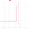
The PWM is turned into an analog signal by low pass filtering it quite slowly. A wild guess is a jump in udc of 100V will take several 100ms to show up in software.noquarter wrote: ↑Thu Mar 05, 2026 6:53 am That just leaves the "500Hz PWM" from the leaf inverter. I'm not really sure what that is in this context, since the ADC on the STM32 is expecting a 0-3.3V analogue input, correct? Either way if the latency out of that is only 2ms, that would be fine, no need for modification there.
Your CAN idea could work. I'm also planning to design a HV -> CAN module for use with Foccci(Cape)
Support R/D and forum on Patreon: https://patreon.com/openinverter - Subscribe on odysee: https://odysee.com/@openinverter:9
Re: Using a PMSM and inverter to generate and regulate a DC voltage
I'll definitely keep the CAN idea as a backup, but it seems logical to me to use the UDCmax function if possible as that could potentially be more reliable and easier to tune, since no PID loop would be involved or the addition of another piece of external hardware. I'll start working on my own voltage sense to bypass the existing hardware, to feed directly to the ADC13 pin on the STM32. Still looking for a way to modify the software low pass filtering.johu wrote: ↑Fri Mar 06, 2026 7:44 pm The PWM is turned into an analog signal by low pass filtering it quite slowly. A wild guess is a jump in udc of 100V will take several 100ms to show up in software.
Your CAN idea could work. I'm also planning to design a HV -> CAN module for use with Foccci(Cape)
If you believe the UDCmax parameter will not work as intended here, then we will not pursue this method.
-
johu
- Site Admin
- Posts: 7182
- Joined: Thu Nov 08, 2018 10:52 pm
- Location: Kassel/Germany
- Has thanked: 552 times
- Been thanked: 1913 times
- Contact:
Re: Using a PMSM and inverter to generate and regulate a DC voltage
Just real quick, here's the line that does the software filtering: https://github.com/jsphuebner/stm32-sin ... l.cpp#L489
It's not as slow as I thought. Replacing the "2" with a "0" would yield no filtering at all. But start out with modifying the HW low passes, they are much slower.
It's not as slow as I thought. Replacing the "2" with a "0" would yield no filtering at all. But start out with modifying the HW low passes, they are much slower.
Support R/D and forum on Patreon: https://patreon.com/openinverter - Subscribe on odysee: https://odysee.com/@openinverter:9
Re: Using a PMSM and inverter to generate and regulate a DC voltage
Excellent, thank you!johu wrote: ↑Wed Mar 11, 2026 7:03 am Just real quick, here's the line that does the software filtering: https://github.com/jsphuebner/stm32-sin ... l.cpp#L489
It's not as slow as I thought. Replacing the "2" with a "0" would yield no filtering at all. But start out with modifying the HW low passes, they are much slower.
The current plan is using this reference board: https://www.digikey.com/en/products/det ... Z/21334078
Which can provide a voltage to our UDC input. On the OI board we will replace the 1 microfarad cap with a 50nF cap which should put the cutoff frequency at 318Hz. I don't know the side effects of going too high with it but 3ms should be perfectly fine.