Prius Gen 3 Inverter Logic Board Support Thread
-
Dylan Witt
- Posts: 123
- Joined: Sat Apr 18, 2020 4:23 am
- Location: Kentucky, USA
- Been thanked: 5 times
Re: Prius Gen 3 Inverter Logic Board Support Thread
This design makes me happy. Also, I have put the electric rx8 build on hold, I got a job building toyota Camrys, Avalon's and 2021 rav4 dual motor hybrid. So here's to a new career and soon to purchase a Tesla and make the electric mazda a full project car. Might even incorporate the new damien board. As long as the board is happy with mg2 spinning faster than mg2.
-
konstantin8818

- Posts: 290
- Joined: Sun Jan 19, 2020 2:33 pm
- Location: Minsk, Belarus
- Has thanked: 2 times
- Been thanked: 10 times
Re: Prius Gen 3 Inverter Logic Board Support Thread
Little off-topic here:
The latest 35-way connector housing design fits perfectly to gen3 inverter:
It is not utilising original red sealant, instead you can fit there any rubber band or air-cured silicone sealant.
For the original adapter plate all you need to do is to grind off 5mm of two corners.
STL attached
The latest 35-way connector housing design fits perfectly to gen3 inverter:
STL attached
-
Jack Bauer

- Posts: 4005
- Joined: Wed Dec 12, 2018 5:24 pm
- Location: Ireland
- Has thanked: 153 times
- Been thanked: 1132 times
- Contact:
Re: Prius Gen 3 Inverter Logic Board Support Thread
Sweet! Need to get a few of those made.
In other news the V1d boards have arrived:)
In other news the V1d boards have arrived:)
- Attachments
-
-
-
I'm going to need a hacksaw
-
bobby_come_lately

- Posts: 486
- Joined: Sun May 03, 2020 5:39 am
- Location: Manchester, UK
- Has thanked: 56 times
- Been thanked: 63 times
- Contact:
Re: Prius Gen 3 Inverter Logic Board Support Thread
Updated this as I have slightly different readings than last night when I took them.
##
Morning all. Hoping to get some ideas about what might be going wrong.
After working fine for a while, my board has thrown a wobbly - though it may have been provoked.
The main symptom is that udc is now locked to 818.37v. Doesn't move at all. It has been working absolutely fine.
Checked the voltages around the board.
- Pin 10 (dcbus2) is at 2.29v
- 3v3 at C32 is now at 3.85v
- 5v at C20/C21/C22/C25 is now at 4.2v
- -5v at the via next to CONN7 is now at -2.89v
This started after I was trying to get wheels spinning. I may have (I did) get a little enthusiastic with putting current into the motor. And there may have been a short elsewhere in my 12v loom. But this problem didn't start immediately after either of those things.
Have done reset, updated firmware etc.
Any pointers very welcome.
-
Jack Bauer
- Posts: 4005
- Joined: Wed Dec 12, 2018 5:24 pm
- Location: Ireland
- Has thanked: 153 times
- Been thanked: 1132 times
- Contact:
Re: Prius Gen 3 Inverter Logic Board Support Thread
Answered in your build thread.
I'm going to need a hacksaw
-
Bigpie

- Posts: 1884
- Joined: Wed Apr 10, 2019 8:11 pm
- Location: South Yorkshire, UK
- Has thanked: 91 times
- Been thanked: 517 times
Re: Prius Gen 3 Inverter Logic Board Support Thread
Has anyone got parameter values for il1gain, il2gain, udcgain, udcofs and tmphs etc or are these something we have to workout for each inverter? I don't have a way of putting a known fixed current through the sensors.
BMW E91 2006
ZombieVerter
GS450h
Outlander Charger DC/DC
Outlander Compressor
Renault Kangoo 36kWh battery
FOCCCI CCS
ZombieVerter
GS450h
Outlander Charger DC/DC
Outlander Compressor
Renault Kangoo 36kWh battery
FOCCCI CCS
-
Jack Bauer
- Posts: 4005
- Joined: Wed Dec 12, 2018 5:24 pm
- Location: Ireland
- Has thanked: 153 times
- Been thanked: 1132 times
- Contact:
Re: Prius Gen 3 Inverter Logic Board Support Thread
Here is a param set from running a gen2 mg2. Should have what you need.
- Attachments
-
- gen3_mg2_gen2_inv_g3_perfect.json
- (1.3 KiB) Downloaded 376 times
I'm going to need a hacksaw
-
Bigpie
- Posts: 1884
- Joined: Wed Apr 10, 2019 8:11 pm
- Location: South Yorkshire, UK
- Has thanked: 91 times
- Been thanked: 517 times
Re: Prius Gen 3 Inverter Logic Board Support Thread
Thanks. I've added the inverter related params to the wiki
BMW E91 2006
ZombieVerter
GS450h
Outlander Charger DC/DC
Outlander Compressor
Renault Kangoo 36kWh battery
FOCCCI CCS
ZombieVerter
GS450h
Outlander Charger DC/DC
Outlander Compressor
Renault Kangoo 36kWh battery
FOCCCI CCS
-
Bigpie
- Posts: 1884
- Joined: Wed Apr 10, 2019 8:11 pm
- Location: South Yorkshire, UK
- Has thanked: 91 times
- Been thanked: 517 times
Re: Prius Gen 3 Inverter Logic Board Support Thread
I've watched the FOC tuning video a few times, but I'm still not sure how I'd know I have the resolver connections right? What behaviour would suggest I have them incorrect?
BMW E91 2006
ZombieVerter
GS450h
Outlander Charger DC/DC
Outlander Compressor
Renault Kangoo 36kWh battery
FOCCCI CCS
ZombieVerter
GS450h
Outlander Charger DC/DC
Outlander Compressor
Renault Kangoo 36kWh battery
FOCCCI CCS
-
m.art.y
- Posts: 713
- Joined: Sat Jun 06, 2020 6:54 pm
- Location: UK/EU
- Has thanked: 38 times
- Been thanked: 37 times
Re: Prius Gen 3 Inverter Logic Board Support Thread
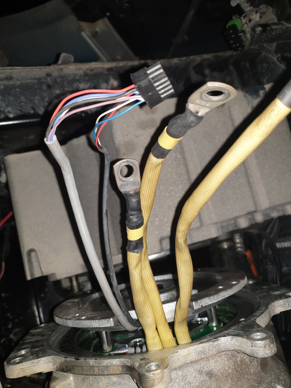
Help! According to data sheet I have 3 phase synchronous permanent magnet motor with 8 poles. Apart from 3 phase wires I have 9 other small wires coming out inside two separate leads. One lead has 4 small wires (which are a touch thinner than the wires in the other lead) and the other lead has 5 wires. The worst part is that resistances does not make any sense at all and I can't find pairs!
4 wire lead:
red and black 384.40 kOhms
white and blue - no match
5 wire lead:
black and blue 12.40 MOhms
black and violet 12.36 MOhms
black and white 12.42 MOhms
blue and violet 8.43 MOhms
blue and white 8.43 MOhms
violet and white 8.50 MOhms
If I change the polarity of the leads the resistance then changes to 25 MOhms or 5 MOhms. I have done so much work sorting out CAN and got everything purchased and set up. Now if I can't solve this resolver problem my project will end there as I have to complete it within few weeks or never. Please help if somebody knows what's going on?
-
johu

- Site Admin
- Posts: 7182
- Joined: Thu Nov 08, 2018 10:52 pm
- Location: Kassel/Germany
- Has thanked: 552 times
- Been thanked: 1914 times
- Contact:
Re: Prius Gen 3 Inverter Logic Board Support Thread
Those values are way out of range, I'd say open circuit. Resolver must be a couple of 10 Ohms.
And again, if anyone contacts me directly without sending some funds along with the question, I consider this rude. I don't owe anyone because I published a design.
And again, if anyone contacts me directly without sending some funds along with the question, I consider this rude. I don't owe anyone because I published a design.
Support R/D and forum on Patreon: https://patreon.com/openinverter - Subscribe on odysee: https://odysee.com/@openinverter:9
-
m.art.y
- Posts: 713
- Joined: Sat Jun 06, 2020 6:54 pm
- Location: UK/EU
- Has thanked: 38 times
- Been thanked: 37 times
Re: Prius Gen 3 Inverter Logic Board Support Thread
This must be some type of encoder then? I'm worried it might be the incremental one because so many wires? I read that you don't recommend incremental encoders with your design but is it possible to use one? I just need to make the car drive and respond to throttle be it not smoothly and not fast.
I apologise for personal message I only did it in distress and did not realize about sending funds as whole project may fall apart and be scrapped because of this discovery. I will fix my mistake.
-
Bigpie
- Posts: 1884
- Joined: Wed Apr 10, 2019 8:11 pm
- Location: South Yorkshire, UK
- Has thanked: 91 times
- Been thanked: 517 times
Re: Prius Gen 3 Inverter Logic Board Support Thread
What motor do you have?
BMW E91 2006
ZombieVerter
GS450h
Outlander Charger DC/DC
Outlander Compressor
Renault Kangoo 36kWh battery
FOCCCI CCS
ZombieVerter
GS450h
Outlander Charger DC/DC
Outlander Compressor
Renault Kangoo 36kWh battery
FOCCCI CCS
-
johu
- Site Admin
- Posts: 7182
- Joined: Thu Nov 08, 2018 10:52 pm
- Location: Kassel/Germany
- Has thanked: 552 times
- Been thanked: 1914 times
- Contact:
Re: Prius Gen 3 Inverter Logic Board Support Thread
It could be, try taking it out of the motor and posting a picture.
Yes incremental, indexed encoders are not well tested to say the least. I wouldn't spend any more time on this because it's a silly choice for a synchronous motors.
You may be better off mounting a Melexis sin/cos chip instead.
Yes incremental, indexed encoders are not well tested to say the least. I wouldn't spend any more time on this because it's a silly choice for a synchronous motors.
You may be better off mounting a Melexis sin/cos chip instead.
Support R/D and forum on Patreon: https://patreon.com/openinverter - Subscribe on odysee: https://odysee.com/@openinverter:9
-
arber333
- Posts: 3795
- Joined: Mon Dec 24, 2018 1:37 pm
- Location: Slovenia
- Has thanked: 166 times
- Been thanked: 411 times
- Contact:
Re: Prius Gen 3 Inverter Logic Board Support Thread
HIm.art.y wrote: ↑Wed Nov 25, 2020 12:31 pm This must be some type of encoder then? I'm worried it might be the incremental one because so many wires? I read that you don't recommend incremental encoders with your design but is it possible to use one? I just need to make the car drive and respond to throttle be it not smoothly and not fast.
Maybe you can use RLS encoder. They have a chip which can sense magnet underneath and can output various signals like sin/cos without excitation. When I get hold of pc I will post you the links to datasheets and schematics.
For that to work you need to make a new fitting for the magnet and the chip pcb both of them mounted in axis center. I think you have access to a mill and lathe...
EDIT: Here are some links...
https://leafdriveblog.wordpress.com/2016/11/16/encoder/
https://www.rls.si/eng/products/rotary- ... tal-flange
https://www.rls.si/eng/fileuploader/dow ... _sheet.pdf
-
Bigpie
- Posts: 1884
- Joined: Wed Apr 10, 2019 8:11 pm
- Location: South Yorkshire, UK
- Has thanked: 91 times
- Been thanked: 517 times
Re: Prius Gen 3 Inverter Logic Board Support Thread
I've just noticed there's some new files in the github repo for the web interface, upload these and go to syncofs.html
Looks like Dima has made a nice interface for tuning.
Looks like Dima has made a nice interface for tuning.
- Attachments
-
BMW E91 2006
ZombieVerter
GS450h
Outlander Charger DC/DC
Outlander Compressor
Renault Kangoo 36kWh battery
FOCCCI CCS
ZombieVerter
GS450h
Outlander Charger DC/DC
Outlander Compressor
Renault Kangoo 36kWh battery
FOCCCI CCS
-
m.art.y
- Posts: 713
- Joined: Sat Jun 06, 2020 6:54 pm
- Location: UK/EU
- Has thanked: 38 times
- Been thanked: 37 times
Re: Prius Gen 3 Inverter Logic Board Support Thread
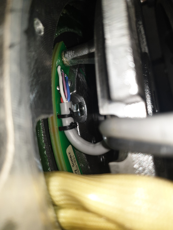
johu wrote: ↑Wed Nov 25, 2020 1:06 pm try taking it out of the motor and posting a picture
I tried pulling the thing out, feels like pulling internal shaft out of the motor, quite large, don't know how it is attached in there don't want to break anything. It has a number on the plate Leroy Somer 15021831 but google search did not produce anything. On the black lead with the 4 wires inside it says RC3. Is it possible to identify it and would it be possible to use it with the gen3 prius open inverter?

-
bobby_come_lately
- Posts: 486
- Joined: Sun May 03, 2020 5:39 am
- Location: Manchester, UK
- Has thanked: 56 times
- Been thanked: 63 times
- Contact:
Re: Prius Gen 3 Inverter Logic Board Support Thread
Nice! Will have to give this a try when my inverter is up and running again.
-
johu
- Site Admin
- Posts: 7182
- Joined: Thu Nov 08, 2018 10:52 pm
- Location: Kassel/Germany
- Has thanked: 552 times
- Been thanked: 1914 times
- Contact:
Re: Prius Gen 3 Inverter Logic Board Support Thread
Ok, definitely no resolver
Hmm, maybe this helps: http://www.leroy-somer.com/documentatio ... 928_en.pdf (page 60)
They mention various feedback devices
Hmm, maybe this helps: http://www.leroy-somer.com/documentatio ... 928_en.pdf (page 60)
They mention various feedback devices
Support R/D and forum on Patreon: https://patreon.com/openinverter - Subscribe on odysee: https://odysee.com/@openinverter:9
-
arber333
- Posts: 3795
- Joined: Mon Dec 24, 2018 1:37 pm
- Location: Slovenia
- Has thanked: 166 times
- Been thanked: 411 times
- Contact:
Re: Prius Gen 3 Inverter Logic Board Support Thread
I post my answer to PM here for others benefit:
I am using my car with a variant of RLS encoder every day now. Albeit i am using commutation outputs with Lebowski inverter. Encoder has different outputs like ABZ incremental or Sin/Cos analog. I recommend you to use the latter with Openinverter because Johannes put in code also this variant of sin/cos signal without excitation.
Also you need to consider encoder mounting. Do you have access to the shaft at the back of the motor?
Can you make an encoder mount in place of original resolver? Be advised encoder comes centered with a round plate. You only need to make a mount that will put this circle in the center of the shaft/magnet.
Also you need to select correct RLS product on basis of your motor.
If you have 8pole motor and you need sin/cos output you may want RMF44AC01SA10 sensor and RMM44A3A00 magnet.
You can use any form of 4 line cable, You need 5V, GND, Sin and Cos lines. Maybe it would be a good idea to have it shielded.
But now that i see you in fact have ABZ encoder on the motor it would be good to test the output on the A and B channels to see how many pulses per revolution they show. Or maybe you have encoder PN written on that PCB? I am interested seeing what would that motor do with ABZ. Is it ACIM or PMSM?
-
m.art.y
- Posts: 713
- Joined: Sat Jun 06, 2020 6:54 pm
- Location: UK/EU
- Has thanked: 38 times
- Been thanked: 37 times
Re: Prius Gen 3 Inverter Logic Board Support Thread
How would I test this? I've only got a multimeter. I don't yet know what ACIM or PMSM stands for and how to verify which one. Shall I start another thread on this? Don't feel good about taking this thread off topic.
-
Bigpie
- Posts: 1884
- Joined: Wed Apr 10, 2019 8:11 pm
- Location: South Yorkshire, UK
- Has thanked: 91 times
- Been thanked: 517 times
Re: Prius Gen 3 Inverter Logic Board Support Thread
I've been following the tuning video, I've got what I thought was a good syncofs, I found a value that doesn't spin with manualid but when I try a low manual id and 3 for manualiq it'll rotate a few times then stop, but my light bulb stays illuminated. Would this indicate I don't yet have a phd in resolvers and need to try another combination or my syncofs is incorrect?
BMW E91 2006
ZombieVerter
GS450h
Outlander Charger DC/DC
Outlander Compressor
Renault Kangoo 36kWh battery
FOCCCI CCS
ZombieVerter
GS450h
Outlander Charger DC/DC
Outlander Compressor
Renault Kangoo 36kWh battery
FOCCCI CCS
-
Jack Bauer
- Posts: 4005
- Joined: Wed Dec 12, 2018 5:24 pm
- Location: Ireland
- Has thanked: 153 times
- Been thanked: 1132 times
- Contact:
Re: Prius Gen 3 Inverter Logic Board Support Thread
No it means you don't use a light bulb while tuning:) The bulb is there during early testing in case you have current sensors setup wrong, resolver wired wrong etc.
Some interesting things going on in this video :
Some interesting things going on in this video :
I'm going to need a hacksaw
-
Bigpie
- Posts: 1884
- Joined: Wed Apr 10, 2019 8:11 pm
- Location: South Yorkshire, UK
- Has thanked: 91 times
- Been thanked: 517 times
Re: Prius Gen 3 Inverter Logic Board Support Thread
Ahh right, thought I'd leave it on to see what current was going through. I'll start again tomorrow. 
BMW E91 2006
ZombieVerter
GS450h
Outlander Charger DC/DC
Outlander Compressor
Renault Kangoo 36kWh battery
FOCCCI CCS
ZombieVerter
GS450h
Outlander Charger DC/DC
Outlander Compressor
Renault Kangoo 36kWh battery
FOCCCI CCS
-
Bigpie
- Posts: 1884
- Joined: Wed Apr 10, 2019 8:11 pm
- Location: South Yorkshire, UK
- Has thanked: 91 times
- Been thanked: 517 times
Re: Prius Gen 3 Inverter Logic Board Support Thread
I've added a lightbulb bypass switch to my Damien danger plank and now spinning my outlander front motor in closed loop FOC.
I'll probably run through tuning again while I wait metal to be delivered, but happy with that for now.
I'll probably run through tuning again while I wait metal to be delivered, but happy with that for now.
BMW E91 2006
ZombieVerter
GS450h
Outlander Charger DC/DC
Outlander Compressor
Renault Kangoo 36kWh battery
FOCCCI CCS
ZombieVerter
GS450h
Outlander Charger DC/DC
Outlander Compressor
Renault Kangoo 36kWh battery
FOCCCI CCS