Page 4 of 10
Re: i3 controller hacking from diyelectriccar.com
Posted: Sat Oct 23, 2021 4:05 pm
by johu
Decided to put it up for sale now:
https://openinverter.org/shop/index.php ... duct_id=72
Will order parts when there's enough interest.
Re: i3 controller hacking from diyelectriccar.com
Posted: Sun Oct 24, 2021 7:33 am
by Scott166
Order placed, thank you for all your work on this
Re: i3 controller hacking from diyelectriccar.com
Posted: Mon Oct 25, 2021 6:27 am
by Hans Gustafsson
Order placed, thank you!
Re: i3 controller hacking from diyelectriccar.com
Posted: Mon Oct 25, 2021 7:54 am
by johu
Nice, getting ready to order parts

Re: i3 controller hacking from diyelectriccar.com
Posted: Mon Oct 25, 2021 4:31 pm
by golfdubcrazy
Awesome work order placed

Re: i3 controller hacking from diyelectriccar.com
Posted: Mon Oct 25, 2021 8:58 pm
by CJW
Order placed, thanks for making it possible for people to build cool electric cars!
Re: i3 controller hacking from diyelectriccar.com
Posted: Tue Oct 26, 2021 7:59 am
by johu
Wow, that was quick

Re: i3 controller hacking from diyelectriccar.com
Posted: Mon Nov 15, 2021 2:40 pm
by johu
The next batch of i3 boards arrived today and work flawlessly.
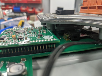
I have to reflow the TPS61175 and the Erni connector by hand. The Erni makes it hard, I bridges several pins back to front on my first attempt. I should be able to ship out the ordered boards by the end of the week.
Re: i3 controller hacking from diyelectriccar.com
Posted: Mon Nov 15, 2021 6:47 pm
by Jack Bauer
Nice work Johannes. Great to see that inverter alive.
Re: i3 controller hacking from diyelectriccar.com
Posted: Tue Nov 16, 2021 11:34 am
by johu
Thanks

More woes. Ampseal pins are out of stock
https://www.digikey.de/products/de?t=331&s=4406
Re: i3 controller hacking from diyelectriccar.com
Posted: Fri Nov 19, 2021 12:40 pm
by golfdubcrazy
Amazing Work can wait to get the motor spinning on the inverter

Re: i3 controller hacking from diyelectriccar.com
Posted: Fri Dec 03, 2021 11:47 am
by johu
Quick heads up to everyone waiting for their order: I'm still waiting for the flippin ampseal pins. Damien put them in the post for me ages ago (they were only available from RS Ireland) and they still haven't arrived.
Re: i3 controller hacking from diyelectriccar.com
Posted: Tue Dec 14, 2021 12:34 pm
by Scott166
I got my board yesterday, I've taken jet engines out of planes, driven 2000 ton freight trains, cut the floor out of an old Mini and this is the scariest thing I've looked at

Re: i3 controller hacking from diyelectriccar.com
Posted: Tue Dec 14, 2021 9:16 pm
by johu
oh and I still have to write an info sheet. Just post here if there are any questions. I'll just make the wifi PW public now: dsEuX51n
Re: i3 controller hacking from diyelectriccar.com
Posted: Wed Dec 15, 2021 7:51 am
by Hans Gustafsson
Is an Olimex ESP8266 module also needed?
Re: i3 controller hacking from diyelectriccar.com
Posted: Wed Dec 15, 2021 10:55 am
by johu
it's included
Re: i3 controller hacking from diyelectriccar.com
Posted: Wed Dec 15, 2021 11:25 am
by golfdubcrazy
Thanks Johu,

Received mine yeasterday

Just a quick one do you have the pinout for the ampseal plug ?
Re: i3 controller hacking from diyelectriccar.com
Posted: Wed Dec 15, 2021 2:04 pm
by johu
Yes, it's similar to the Tesla output:
- 12V
- BRAKE_IN
- PRECHARGE_OUT
- CANL
- CANH
- DCSW_OUT
- FORWARD_IN
- REVERSE_IN
- 5V (OUT)
- RESOLVER_S2/ENCODER_A
- GND
- RESOLVER_S1
- THROTTLE1
- THROTTLE2
- RESOLVER_R1
- RESOLVER_S3/ENCODER_B
- MTEMP+
- MTEMP-
- RESOLVER_S4
- EMCYSTOP_IN
- GND
- RESOLVER_R2
- START_IN
Anyone want to extend the wiki page?
https://openinverter.org/wiki/I3_inverter
Re: i3 controller hacking from diyelectriccar.com
Posted: Thu Dec 16, 2021 7:19 pm
by Hans Gustafsson
The 12-pin connector from the resolver / motor temp that connects to the BMW brainboard, is the ERNI MiniBridge Koshiri Messerleiste 12-pin, geared, SMT, Art-No. 294920 and it is available for purchase mounted on a handy adapter card.
https://www.erni-x-press.com/en/artikel/kit/169219.html
https://www.erni.com/fileadmin/import/p ... 000162.PDF
https://www.erni-x-press.com/de/artikel ... 94920.html
Re: i3 controller hacking from diyelectriccar.com
Posted: Sat Dec 18, 2021 9:42 am
by MrX
Exciting times! Lots of new people with new inverters!
I've been working on some mechanical integration bits and pieces, hopefully some that will help other members.
1: If you are planning on using the shield mounted under the inverter, you will have to knock out the centre post as it sticks up into the pins on the adapter PCBA. I used a large step drill and slowly worked my way through it.

- adapter PCBA shield mod
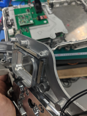
2: One of the posts for the connector mount casting collides with the inverter, I just milled this down ~7mm and halfway across the post. The screw will need loctite to seal from the topside as you expose the threads in doing this.

- Post mod connector casting

- Post mod connector casting 2
3. Lastly, I've made some waterjet cut blanking plates to close off cooling for the charger and DCDC inside the housing. This is just to remove them whilst they aren't doing anything useful and remove some weight from the assembly. Unfortunately it's not straightforward to do this, as some posts have to be machined down for these flat plates to fit, and this exposes one of the threads from the liquid side. I've hydraulically sealed this one, so it shouldn't be a problem (fingers crossed). If people want DXF files for these I can definitely send some links. They are definitely
not perfect, and will need some modification to fit well. I did as best I could for hole placement for a first-pass. Fine for now though!

- Blanking plate charger

- Blanking plate DCDC
All in all, excited to get a spinning motor! I've worked out the resolver, but not sure which of the 4 permutations I have. I was using an inverter before that could compensate for switching the sin and cos polarity, so I may need to tweak the wiring for it to work with the openinverter.
Thanks for the work so far Johannes!
Re: i3 controller hacking from diyelectriccar.com
Posted: Sat Dec 18, 2021 11:26 am
by johu
Thanks for posting

I though I had cleared that screw post by now, oh well. Can't move the adapter PCB down any further because I believe it will then collide with the top cover.
Re: i3 controller hacking from diyelectriccar.com
Posted: Sun Dec 19, 2021 3:00 am
by MrX
johu wrote: ↑Sat Dec 18, 2021 11:26 am
I though I had cleared that screw post by now, oh well. Can't move the adapter PCB down any further because I believe it will then collide with the top cover.
I just remembered you had mentioned that you fixed the screw post collision on the new adapter board rev, that would be it! I think it might be close still, but it probably will not need as much cut out of it as mine did.
Re: i3 controller hacking from diyelectriccar.com
Posted: Sun Dec 26, 2021 5:12 pm
by Hans Gustafsson
Pinout with the colors for the resolver, suggestions and not verified.
1. 12V
2. BRAKE_IN
3. PRECHARGE_OUT
4. CANL
5. CANH
6. DCSW_OUT
7. FORWARD_IN
8. REVERSE_IN
9. 5V (OUT)
10. RESOLVER_S2/ENCODER_A___: Blue (Sin2, Sin L)
11. GND
12. RESOLVER_S1______________: Brown (Sin1, Sin H)
13. THROTTLE1
14. THROTTLE2
15. RESOLVER_R1______________: Yellow (REF1, Ex H)
16. RESOLVER_S3/ENCODER_B___: Red (Cos1, Cos H)
17. MTEMP+
18. MTEMP-
19. RESOLVER_S4______________: White (Cos2, Cos L)
20. EMCYSTOP_IN
21. GND
22. RESOLVER_R2______________: Green (Ref2, Ex L)
23. START_IN
![Image]()
With 12 pin adapter card and solder directly to the card.
Re: i3 controller hacking from diyelectriccar.com
Posted: Sun Dec 26, 2021 10:56 pm
by johu
Interesting! So the resolver is not connected via the main connector? I mean in BMW OEM design. What are the other signals?
Congratulations on your compacting work

Re: i3 controller hacking from diyelectriccar.com
Posted: Mon Dec 27, 2021 6:49 am
by Hans Gustafsson
johu wrote: ↑Sun Dec 26, 2021 10:56 pm
Interesting! So the resolver is not connected via the main connector? I mean in BMW OEM design. What are the other signals?
Congratulations on your compacting work

The motor seems to have 2 temp sensors which are blue-gray and red-gray which are 7-8 and 9-10 on the adapter card and I have connected one. 11-12 unknown.