Tesla Charger Support Thread
-
Jack Bauer

- Posts: 4005
- Joined: Wed Dec 12, 2018 5:24 pm
- Location: Ireland
- Has thanked: 153 times
- Been thanked: 1132 times
- Contact:
Re: Tesla Charger Support Thread
That's not possible. You would need two logic boards.
I'm going to need a hacksaw
Re: Tesla Charger Support Thread
Hi all I have a hypothetical question for you all.
I have a Gen 3 charger and 2 conversions. I would like to keep the charger out of the car and in my shed.
I have single phase 230 volt and 14kw circuit is it possible to?
Install chademo plugs on both cars so I can charge in town and then plug the Gen 3 in at home as a chademo DC out of the charger?
I guess I will need to cool the charger some how.
Don’t know a thing about chademo and what’s needed.
Thanks in advance Conrad
-
Kevin Sharpe

- Posts: 1339
- Joined: Fri Dec 14, 2018 9:24 pm
- Location: Ireland and US
- Been thanked: 10 times
Re: Tesla Charger Support Thread
In each car you'll need a CHAdeMO interface controller and a couple of contactors. You could use the kit from New Electric (here) or use the EVTV software that Damien was working on.
For the charger you'll need to develop a CHAdeMO master controller. I'm not aware of any open source solutions and therefore it would be a big task.
Why not dump the CHAdeMO requirement and simply use a waterproof connector for the charger and battery? You'd want some basic contactor control logic but no communications protocol would be needed
This is a personal post and I disclaim all responsibility for any loss or damage which any person may suffer from reliance on the information and material in this post or any opinion, conclusion or recommendation in the information and material.
Re: Tesla Charger Support Thread
Hi Damien
i ask you, if you give me the o.k. to make a equal board with a ESP32 on it.
Could it be, that you give me the permission to use your PCB file as basis.
With wich disign tool do you made it?
i ask you, if you give me the o.k. to make a equal board with a ESP32 on it.
Could it be, that you give me the permission to use your PCB file as basis.
With wich disign tool do you made it?
-
Kevin Sharpe
- Posts: 1339
- Joined: Fri Dec 14, 2018 9:24 pm
- Location: Ireland and US
- Been thanked: 10 times
Re: Tesla Charger Support Thread
It's open source... see the license here;
https://github.com/damienmaguire/Tesla- ... er/LICENSE
DesignSpark iirc
This is a personal post and I disclaim all responsibility for any loss or damage which any person may suffer from reliance on the information and material in this post or any opinion, conclusion or recommendation in the information and material.
Re: Tesla Charger Support Thread
Thanks Kevin
I was thinking the same thing just a Anderson plug for now until things develop more.
Cheers Conrad
I was thinking the same thing just a Anderson plug for now until things develop more.
Cheers Conrad
Re: Tesla Charger Support Thread
i can't open the files with DesignSpark.
Newest downloaded Version!
Newest downloaded Version!
-
Kevin Sharpe
- Posts: 1339
- Joined: Fri Dec 14, 2018 9:24 pm
- Location: Ireland and US
- Been thanked: 10 times
Re: Tesla Charger Support Thread
Have you tried opening another file to ensure your DesignSpark installation is working? What error do you get when you try to open the charger files?
It's always a good idea to post the software version you are using.
This is a personal post and I disclaim all responsibility for any loss or damage which any person may suffer from reliance on the information and material in this post or any opinion, conclusion or recommendation in the information and material.
Re: Tesla Charger Support Thread
Is there guidance available on how to hook up Single Phase US power to the charger (I'm connecting via a HVJB), and any special provisions for grounding?
-
Jack Bauer
- Posts: 4005
- Joined: Wed Dec 12, 2018 5:24 pm
- Location: Ireland
- Has thanked: 153 times
- Been thanked: 1132 times
- Contact:
Re: Tesla Charger Support Thread
This Manual may help :
https://github.com/damienmaguire/Tesla- ... manual.pdf
https://github.com/damienmaguire/Tesla- ... manual.pdf
I'm going to need a hacksaw
Re: Tesla Charger Support Thread
What would be the best way to shut off the charger if there is an issue with battery temperature or cell voltages? Disconnect the control signal, or just the 12v power supply to the charger? Also, does the charger taper down amperage as it approaches max voltage?
-
tom91

- Posts: 2962
- Joined: Fri Mar 01, 2019 9:15 pm
- Location: Bicester, Oxfordshire
- Has thanked: 330 times
- Been thanked: 847 times
Re: Tesla Charger Support Thread
Turning off the 12V enable signal, you could go as far as disconnecting the power if you really want to play it safe.
Yes the charger tapers, currently only by way of going into constant voltage mode.
Yes the charger tapers, currently only by way of going into constant voltage mode.
-
doobedoobedo
- Posts: 264
- Joined: Sat Jan 12, 2019 12:39 am
- Location: UK
- Been thanked: 1 time
-
xp677
- Posts: 442
- Joined: Sat Jul 27, 2019 10:53 am
- Location: UK
- Has thanked: 1 time
- Been thanked: 15 times
Re: Tesla Charger Support Thread
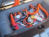
Just a random bit of info on the Gen 3 chargers. Not sure if this deserves it's own thread so here is is:
It is possible, albeit rather difficult, to extract the logic board from these controllers. I managed it today in around 3 hours. I'm going to draw up a replacement, blank board with just the connectors and pin headers, which would allow an external controller (such as Damiens) to connect to the Tesla charger via the original 20-pin connector.
For anyone attempting this at home, I've included a picture which highlights the solder joints to remove. Note the tiny component between Q8 and Q5 (looks like a thermistor, but meters open-circuit), and the transformer, which for both of my modules snapped off the mounts for the pins. Still usable, but it's now going to be trickier to install the modules.
One of my inductors came free from the adhesive below, this was handy as the inductor near the DC output has very heavy gauge wire, my 65W soldering iron struggled to remove it.
Also of note is that R1 on both of my modules has burnt out. The nearby resistors in series with it are all 100 ohms, I assume this is too. The traces on the board are damaged as well. I'll find a way to replace this, I'm not sure if there was damage to my board or if this is a common issue.
One thing which would help me out would be identifying the two connectors on this board. Especially the 20-pin external connector (looks like an Ampseal, but has no markings),a s I'd need a mating connector for this.
Edit: Mating connector for the 20 pin external connector is Molex 33472-2006. Pins for this are 33012-3002 for 18-20awg, depending on wire size required, you can use 2001-2003 and others as well. Cavity plugs are 34345-0001
Internal connector is a TE model, I won't be using this on my charger so haven't looked it up.


-
xp677
- Posts: 442
- Joined: Sat Jul 27, 2019 10:53 am
- Location: UK
- Has thanked: 1 time
- Been thanked: 15 times
Re: Tesla Charger Support Thread
As promised, here's an Eagle schematic, board layout, and gerber files for a basic breakout board which could replace the factory charger controller and would work with Damiens Gen3 controller. I've allowed for the controller to be placed inside the charger housing (there is space where the supercharger contactors live) or external.
The routing is an "autorouter special", I've checked it and it looks OK. The 24-pin connector is maybe too close to the edge of the board but I made the pads oversized so probably fine.
Completely untested, all dimensions and hole placements are from vernier measurements of the original board, accuracy is not guaranteed. But everything is here to get you started.
I took a guess from the documentation for Damiens controller that the "Activate" pins on Damiens charger are the 5V Power to the boards, and the "Enable" pins are the 3v3 signals directly from the ATSAM3X8E chip. That's how i've wired this. If I'm wrong, it will still work as these pins can be swapped when wiring a mating connector.
For the 8 pin module connectors, I'd use 2x8 90 degree pin header, and remove the lower row of pins, leaving the plastic housing. That looks like what Tesla has done. I used through-hole for this rather than surface mount - I prefer that for connectors whenever possible.

- Attachments
-
- tesla_gen3charger_breakout.zip
- (57.88 KiB) Downloaded 514 times
-
Roadstercycle
- Posts: 118
- Joined: Mon Sep 23, 2019 10:28 pm
- Location: California
- Has thanked: 3 times
- Been thanked: 2 times
- Contact:
Re: Tesla Charger Support Thread
Hi everyone, I am going to get a Damien board for a Gen 2 charger and wondering if there is a specific charger part number that is known not to work, I see the same serial numbers but they end with different letters. h, k, L, J, C. I want to avoid buying an expensive dust collector because I bought the wrong one. I already bought the control board for the Tesla performance motor so I'm all in.
-
Kevin Sharpe
- Posts: 1339
- Joined: Fri Dec 14, 2018 9:24 pm
- Location: Ireland and US
- Been thanked: 10 times
Re: Tesla Charger Support Thread
afaik no such list has been published. We have various Gen 2 chargers in the workshop and we hope to test them in a couple of weeks and publish the results here.Roadstercycle wrote: ↑Sat Sep 28, 2019 3:27 pm if there is a specific charger part number that is known not to work
This is a personal post and I disclaim all responsibility for any loss or damage which any person may suffer from reliance on the information and material in this post or any opinion, conclusion or recommendation in the information and material.
-
Roadstercycle
- Posts: 118
- Joined: Mon Sep 23, 2019 10:28 pm
- Location: California
- Has thanked: 3 times
- Been thanked: 2 times
- Contact:
Re: Tesla Charger Support Thread
Kevin Sharpe wrote: ↑Sat Sep 28, 2019 5:31 pmafaik no such list has been published. We have various Gen 2 chargers in the workshop and we hope to test them in a couple of weeks and publish the results here.Roadstercycle wrote: ↑Sat Sep 28, 2019 3:27 pm if there is a specific charger part number that is known not to work
Thank you Kevin,
How about ones that are working, that will narrow it down a bit.
-
et0
- Posts: 132
- Joined: Sun Oct 13, 2019 8:06 pm
- Location: Scotland
- Has thanked: 15 times
- Been thanked: 6 times
Re: Tesla Charger Support Thread
Hi all,
I am thinking about using an upcoming trip to the US to bring back a Gen 2 charger in my luggage... Any obvious problems with that? Does anyone know what they weigh?
Also, as above, I would really appreciate any hints from people using one with Damien's board, which model number worked for you.
Thank you!
-
Kevin Sharpe
- Posts: 1339
- Joined: Fri Dec 14, 2018 9:24 pm
- Location: Ireland and US
- Been thanked: 10 times
Re: Tesla Charger Support Thread
This is a personal post and I disclaim all responsibility for any loss or damage which any person may suffer from reliance on the information and material in this post or any opinion, conclusion or recommendation in the information and material.
-
et0
- Posts: 132
- Joined: Sun Oct 13, 2019 8:06 pm
- Location: Scotland
- Has thanked: 15 times
- Been thanked: 6 times
Re: Tesla Charger Support Thread
Fantastic, thank you.
Question for Jack Bauer or anyone else who might know: when are bare boards for the Gen 2 charger controller likely to be back in stock?
Question for Jack Bauer or anyone else who might know: when are bare boards for the Gen 2 charger controller likely to be back in stock?
Re: Tesla Charger Support Thread
Hi,
Is it possible to program the controller in such a way that one can charge 230V / 16A single-phase or 3x400V / 16A multi-phase without changing programming / wiring in between? Does the controller start when all three modules are switched to "on", but only one is energized?
Is it possible to program the controller in such a way that one can charge 230V / 16A single-phase or 3x400V / 16A multi-phase without changing programming / wiring in between? Does the controller start when all three modules are switched to "on", but only one is energized?
-
et0
- Posts: 132
- Joined: Sun Oct 13, 2019 8:06 pm
- Location: Scotland
- Has thanked: 15 times
- Been thanked: 6 times
Re: Tesla Charger Support Thread
As far as I understand it you will need a set of contactors to swap between single phase (paralleled inputs) and 3 phase. Possibly the european version gen 3 charger has this hardware built in. I've only just started researching so hopefully someone more knowledgeable will jump in.Jack-Lee wrote: ↑Wed Oct 16, 2019 5:12 pm Hi,
Is it possible to program the controller in such a way that one can charge 230V / 16A single-phase or 3x400V / 16A multi-phase without changing programming / wiring in between? Does the controller start when all three modules are switched to "on", but only one is energized?
-
Kevin Sharpe
- Posts: 1339
- Joined: Fri Dec 14, 2018 9:24 pm
- Location: Ireland and US
- Been thanked: 10 times
Re: Tesla Charger Support Thread
The Gen 2 charger contains three independent ~3.3kW chargers. By default each charger is wired to a different phase so you get ~3.3kW when plugged into single phase and ~9.9kW when plugged into three phase.Jack-Lee wrote: ↑Wed Oct 16, 2019 5:12 pmIs it possible to program the controller in such a way that one can charge 230V / 16A single-phase or 3x400V / 16A multi-phase without changing programming / wiring in between? Does the controller start when all three modules are switched to "on", but only one is energized?
Tesla did produce an external module that physically switched the AC inputs to support ~6.6kW single phase. Very few of these were deployed because most people who wanted higher power just installed a second charger wired in parallel to deliver ~6.6kW single phase and 19.8kW three phase.
I have two chargers in my bus and will confirm this all works as expected with Damien's controller
This is a personal post and I disclaim all responsibility for any loss or damage which any person may suffer from reliance on the information and material in this post or any opinion, conclusion or recommendation in the information and material.
-
tom91
- Posts: 2962
- Joined: Fri Mar 01, 2019 9:15 pm
- Location: Bicester, Oxfordshire
- Has thanked: 330 times
- Been thanked: 847 times
Re: Tesla Charger Support Thread
The way the modules are controlled; the open-source board reads EVSE current limit and then sends the current limit to the modules.
You only tell the open-source board if the modules are wired for single or three phase. As the current limit from the EVSE is per phase.
Thus if you are hooked to an EVSE, single or three phase does not matter to the open-source board it will still only see a 16A signal from the EVSE.
On single phase only one module will actually do any work other two will just complain there is no AC voltage.
Verified multiple times here at Zero-EV.