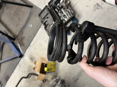
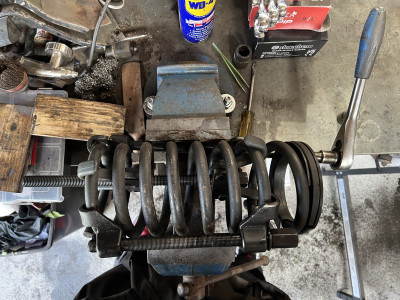
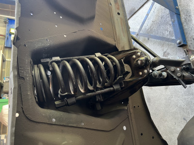
Getting the springs back in was a bit of a pain. To be honest, I’m not sure how I got them out in the first place. No matter what way I arranged them, the spring compressors would get in the way and I couldn’t fit the whole lot into the shock tower. In the end, the solution was to partially compress a spring with one set of compressors, then put another set of compressors on and compress the spring the rest of the way. The second set would start from a fully extended position but be able to grip the spring at the very top and bottom. The spring is always under some compression when in the car - even when the wheels are fully off the ground. When decompressing the spring was (more or less) fully seated in the tower right before the compressors reached their fully extended point.


I have some new shocks to go in the front. But I’ve not been able to fit them yet. The bottom of the shock attaches to the spring perch in the upper arm. The whole upper arm is new and the spring perch is still quite stiff. I couldn’t bend it at all by hand and it would only budge a little when I put a piece of timber in there to lever it. This was in part why the springs were so hard to get back in. One side of the perch was sitting up so high. And now even though the springs are back in, they’re not pushing down enough on the perch to level it out. So, I’ll put the wheels back on and put the wheels on the ground. I think this will squash the springs more and straighten out the spring perches. I’ll need to be careful though when jacking up the front of the car again to make sure that the shocks don’t get bent from the perches twisting them.
Axle
The axle was in pretty decent shape. It was a bit covered in crud and the brake flex hose was looking a bit rough, but apart from that, all it really needed was a clean up. Here’s the ‘before’.
I just went at it with a polycarbide disc, wire wheel and so on to clean it up. I gave it a few coats of paint and it looks great now.
I got fresh u-bolts to hold the axle to the leaf springs. The brackets are original, they just got a clean up and a lick of paint.
The flex line acts as a brake line splitter. The flex line is the input (obviously). It then has two outputs, one for each rear wheel. I have a new flex line to go on and I’ll run fresh brake lines while I’m at it.
The flex line assembly also acts as vent for the inside of the axle. The hole faces up, so, to avoid water ingress, it looks like it had a little bit of rubber tube attached and tilted over. There was only a tiny little bit of the tube still attached to the vent. Must have got ripped off at some point. There’s probably a little tab on the underside of the body somewhere that’s supposed to hold the end of the tube. I’ll replace it later on.
Yes, that shock is upside down.
I also took the opportunity, while the diff was out, to replace the oil. When it’s in the car, you have to suction the oil out. Easier to just tip the diff over while it’s out and let it drain itself.
The oil smelled … interesting. Sort of organic, but very strong. It was really very black so who knows when it was last changed.
I put around 500ml of fresh oil in, sloshed it around (cranked the input shaft a lot), drained it again, and filled it up. I’ll probably run it a bit and do at least one more flush like this. The oil is still quite black. I don’t know how well this diff is going to hold up to EV motor torque, so I don’t want to invest an awful lot in it, but I also want to give it a fighting chance.
Little video here :
https://peertube.chrskly.net/w/bSQ1FvpocnPqh3fZmjXw5j
Disc brake conversion
The original 200 cubic-inch I6 engine that this car had made about 120 horsepower (when it left the factory 60 years ago). I plan to use the inverter from a Toyota Prius when converting this car to an EV. The maximum current that this inverter can pump out is around 500A. Above that some safeties kick in and shut you down. When full, my pack will sit at almost 400V. That means the maximum power output of the inverter will be something in the region of 200kw (500A * 400V = 200kW). 200kw is equivalent to about 270 horsepower. So, it’s safe to say that the car will be getting a major power upgrade. This car had options for a much larger and more powerful engines from the factory. But a power boost like this is definitely a reason to do an upgrade on the braking system from the stock drum brakes.
When it comes to brake upgrade kits there are more options available for the more popular V8 engined cars. However, the V8’s have a different setup to the I6 cars. For one, the V8’s have a five lug wheel setup, while the I6 only have a four lug. Also, the spindles on the V8’s are a little larger. There are still a few options when it comes to the I6 though.
One approach is to buy a small kit which allows you to fit the brakes from a newer mustang to these classics. This would probably be an easier and more economical way for me to go if I lived in the U.S.. I could go to a breakers yard and easily source old calipers and so on. But that’s not really an option for me. Not a lot of mustangs in breakers yards here.
There are some European-based websites that sell conversion kits. They look fine, but I’m not sure what you do when it comes time to replace the pads or discs. It could be that they’re pretty ‘standard’ parts, but I wasn’t sure.
In the end, I got this Wilwood conversion kit. It was a bit more expensive than some of the other kits, but it includes everything and I know that in the future I’ll be able to get replacement parts. Every single piece in the kit has its own part number.
Plus, it looks pretty damn cool.

Fitting this kit was very straightforward. The hub/disc assembly all bolts together. You put a bearing in the front and another in the back. Then the whole thing goes on the spindle. A bracket connects to the old hardware mounting points on the spindle and the caliper connects to that. You need the original spindle washer and nut, but everything else is new.
I’ve not plumbed it in at all yet as I need to run all new brake lines.
I’ll also be putting in an iBooster. It looks like it will possibly fit. It might clash slightly with the steering column ’tube’.
Next step here is to find the old brake cylinder (I have no idea where I put it) and start comparing the pushrods. I’ll need to get the old brake pedal and see how it looks fit-wise with the iBooster. Hopefully there won’t be much modification required.
Wiring
I’ve also re-re-re-thought the low-voltage wiring. I was planning to make some PCBs that would take fuses and relays directly. But that was just making things more complicated than they needed to be. I was concerned around complexity in the logic of what got turned on when. For example, the coolant pump will need to come on when driving AND when charging. Plus I want to do things like allow the BMS to disable driving when the battery is empty and disable driving when charging. The idea was to capture all of this logic in a PCB. But, really, when I boiled it all down, it only really came down to:
Things that turn on when the ignition is on
Things that turn on when we’re charging
Things that turn on when the ignition is on OR when charging
Drive inhibition happens when charging or when the BMS says so
Accomplishing all of that really only needs a handful of diodes and for all of the above to be on relays. So, I still have a little PCB, but just for the handful of diodes.
For everything else, I bought a few of these nice Littelfuse fuse/relay boxes. The build quality is really nice. They take mini fuses and ISO280 relays, so it’s all very compact. They have 60 pins so that’s 30x fuses, or 12x SPST relays (plus 6x fuses), or 8x SPDT relays (plus 6x fuses).
I’ll put two in the engine bay, one under the dash, and one in the boot.
The wiring diagram is still much a work in progress.
The gathering
I’ve also started to gather all of the bits together in one spot. I’ve been collecting all of this stuff over such a long time, it’s all scattered all over the place.
Some of the bits include …
- Brakes
- New brake lines
- iBooster
- New brake fittings for the whole car
- Gen1 iBooster plug kit from EVCreate
- Brake line reducers from EVCreate to fit 4.75mm brake lines on the iBooster
- Low voltage wiring
- Busbars
- Fuse boxes
- Lots of Deutsch plugs/sockets for various bits of low-voltage wiring
- Heating/Cooling
- A couple of small, crappy rads - will probably get something better
- HV water heater from an MG
- A couple of 12V water heaters from a Mercedes (?). May not use.
- Lots of 19mm coolant hose (not shown)
- Various water pumps
- Charging
- Custom BMS
- CHAdeMO and CCS charge ports
- LIM
- HV sense board for LIM from EVCreate
- Custom CHAdeMO charge controller
- MG ZS Charger
- Batteries
- Nice HV plugs/sockets to connect batteries to HVJB
- Safety disconnect / fuse from a Hyundai
- 5V PSUs for the BMS CSCs
- Misc
- Some junction boxes
- Contactors
- Pre-charge resistor

