Dynamic PWM modulation in STM32-SINE FOC to increase the inverter lifetime
Posted: Sun Feb 01, 2026 7:16 pm
This is a separate thread from this post. I went digging through old OEM inverter/DSP asm code and fell into the PWM rabbit hole. I checked most of open source foc codebases if anyone implements any optimizations like that and to my surprise I found none, maybe for a reason. My current goal is simple: possibly reduce switching losses (less heat) without touching the core FOC current controllers, while operating at somewhat silent PWM carrier frequency. My reasoning for this research is that using the stock OEM firmware in my inverter seems to cause bond wire fracturing from heat stress, with observed failure of IGBT every 40ish thousand km. I believe that mean time between failures can be improved here. I have no clue how often zombified inverters show signs of failure, so feel free to chip in, if this is even a problem. I don’t have a proper test bench yet, so for now I’m sharing findings + a proposed investigation plan.
0) What does a “modulation scheme” actually change?
FOC produces a desired voltage vector. PWM modulation turns that into 3 phase duties (A/B/C) by deciding:

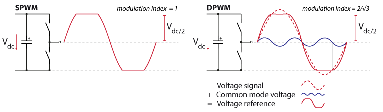
1) Continuous vs discontinuous PWM in simple terms
Continuous PWM (all three legs keep switching all the time)
Discontinuous PWM (DPWM) (intentionally “clamp” one leg to +DC or -DC for parts of the cycle)
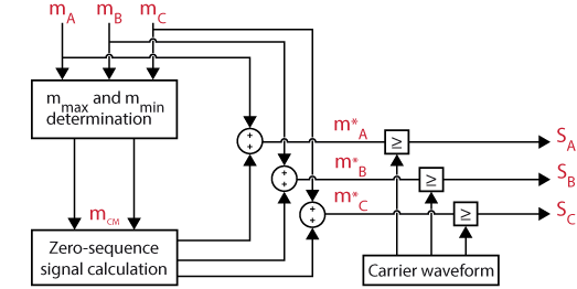
And a block diagram view of “zero-sequence injection”:
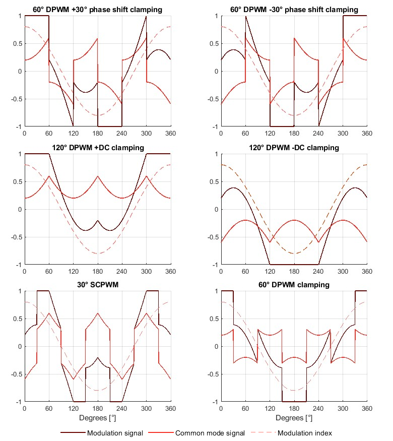
Overview of common DPWM variants:
Why this matters (short version)
FOC modulation is continuous SVPWM common-mode injection + short-pulse suppression. No DPWM variants exist in STM32-SINE FOC today.
3) Proposal A: add DPWMMIN / DPWMMAX via the existing common-mode injection (small change)
stm32-sine already centralizes the common-mode offset. That makes DPWMMIN/MAX a relatively small modulation-layer change:
4) Proposal B: optional dynamic carrier frequency (bigger change)
Carrier frequency (17.6 / 8.8 / 4.4 kHz in stm32-sine) is a separate knob. Lower carrier reduces switching loss, but can increase audible content and current ripple, and it’s more invasive to change safely at runtime. Reading the threads trying to tune motors for foc here at different carrier frequencies makes me think that this is no go at this point, so just feel free to skip this idea at this point.
If attempted, it should be staged:
Questions
1) Has anyone tested DPWMMIN/DPWMMAX/any other DPWM schemes in stm32-sine FOC or any other inverter for thermal benefit vs side effects?
2) Any known pitfalls with current sampling / torque ripple when a leg is clamped for long intervals?
3) If adding dynamic pwm carrier f switching, what is the safest staging approach in stm32-sine without upsetting loop timing? What gotchas could be here stopping a safe implementation?
0) What does a “modulation scheme” actually change?
FOC produces a desired voltage vector. PWM modulation turns that into 3 phase duties (A/B/C) by deciding:
- how much time we spend in the zero states (000 / 111), and
- how often each inverter leg actually commutates (switches).
1) Continuous vs discontinuous PWM in simple terms
Continuous PWM (all three legs keep switching all the time)
- SPWM: classic “3 sine refs vs triangle carrier”. Simple, but not the best DC-bus utilization.
- SVPWM: injects a common-mode offset so you use the DC bus better (more usable voltage before clipping), often lower distortion than plain SPWM.
- THIPWM: add 3rd harmonic (commonly 1/6) to extend linear range; in practice it’s very close to SVPWM min/max injection in the linear region.
Discontinuous PWM (DPWM) (intentionally “clamp” one leg to +DC or -DC for parts of the cycle)
- DPWMMIN / DPWMMAX: choose the common-mode so either the minimum or maximum phase gets clamped for long intervals. Fewer commutations → lower switching loss.
- DPWM0/1/2/3 etc: a family of clamped patterns that move the clamp window around the electrical cycle. Which one is best depends on operating point (power factor angle / field weakening / modulation index).
And a block diagram view of “zero-sequence injection”:
Overview of common DPWM variants:
Why this matters (short version)
- Switching losses are strongly tied to commutations. DPWM reduces commutations, so switching loss can drop noticeably at high modulation / high power. More switching losses = more thermal stress on the junction and bond wires, even if it is well hidden by an overengineered package cooling loop.
- SVPWM/THIPWM improve DC-bus utilization (more voltage headroom before overmodulation).
- No single PWM pattern is “best everywhere”, so hybrid/adaptive strategies show up a lot in literature.
FOC modulation is continuous SVPWM common-mode injection + short-pulse suppression. No DPWM variants exist in STM32-SINE FOC today.
- Common-mode offset is exactly
Code: Select all
(min + max) / 2 - Applied in the FOC inverse Park/Clarke path
- Only clamping is “short pulse suppression” near 0% or 100% duty, not sector-based DPWM
3) Proposal A: add DPWMMIN / DPWMMAX via the existing common-mode injection (small change)
stm32-sine already centralizes the common-mode offset. That makes DPWMMIN/MAX a relatively small modulation-layer change:
- SVPWM (existing):
Code: Select all
offset = (min+max)/2 - DPWMMIN: choose offset to clamp the minimum phase
- DPWMMAX: choose offset to clamp the maximum phase
- More elaborate DPWM schemes could be implemented after that with dynamic switching depending on operating region.
4) Proposal B: optional dynamic carrier frequency (bigger change)
Carrier frequency (17.6 / 8.8 / 4.4 kHz in stm32-sine) is a separate knob. Lower carrier reduces switching loss, but can increase audible content and current ripple, and it’s more invasive to change safely at runtime. Reading the threads trying to tune motors for foc here at different carrier frequencies makes me think that this is no go at this point, so just feel free to skip this idea at this point.
If attempted, it should be staged:
- disable PWM outputs cleanly
- re-init timer period/repetition counter
- update anything tied to timing (PI dt/calling frequency, duty scaling, min-pulse meaning)
- add hysteresis + dwell time to avoid mode flapping
This is skethy imo, so just food for thought.
- A/B temperature rise: SVPWM vs DPWMMIN/MAX at same carrier frequency
- low-speed smoothness, audible behavior, when and to what a dynamic switching scheme should be applied.
- scope gate timing and deadtime margins
- if pwm carrier f switching is added: confirm dt/duty scaling stability
- Chalmers PMSM drive PWM comparison + operating regions:
https://publications.lib.chalmers.se/re ... 256161.pdf - Holtz PWM survey (review):
https://www.semanticscholar.org/paper/P ... 0afe192274 - Holmes & Lipo book (PWM bible):
https://books.google.com/books/about/Pu ... Gi1AjSfpcC - DPWM family, generalized discontinuous PWM (algorithm paper):
https://users.metu.edu.tr/hava/apec97.pdf - imperix explainer (visuals for SVPWM and DPWM):
https://imperix.com/doc/implementation/ ... techniques
https://imperix.com/doc/implementation/ ... inuous-pwm - Deadtime and commutation effects overview:
https://vbn.aau.dk/ws/files/329318065/e ... 196_v2.pdf - IGBT reliability and thermal cycling context:
https://www.researchgate.net/publicatio ... g_lifetime
https://assets.danfoss.com/documents/la ... 000201.pdf
Questions
1) Has anyone tested DPWMMIN/DPWMMAX/any other DPWM schemes in stm32-sine FOC or any other inverter for thermal benefit vs side effects?
2) Any known pitfalls with current sampling / torque ripple when a leg is clamped for long intervals?
3) If adding dynamic pwm carrier f switching, what is the safest staging approach in stm32-sine without upsetting loop timing? What gotchas could be here stopping a safe implementation?