Mini Mainboard: Difference between revisions
No edit summary |
No edit summary |
||
| Line 1: | Line 1: | ||
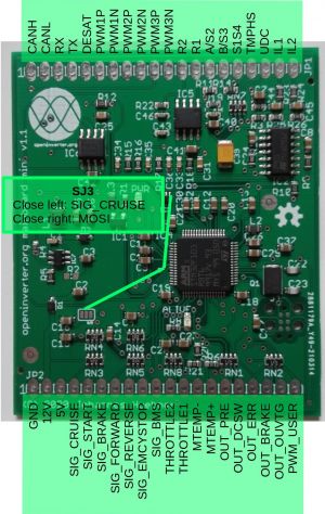
[[File:Mini mainboard front.jpg|thumb|Mini mainboard front]] | [[File:Mini mainboard front.jpg|thumb|Mini mainboard front]] | ||
The mini mainboard is the smallest form factor openinverter motor control board. It has the same functionality as the | The mini mainboard is the smallest form factor openinverter motor control board. It has the same functionality as the [[Main Board Version 3]] but offloads a few components. It is meant to be used as a daughter board on top of an adapter board. The adapter board must (or may) implement: | ||
* The Wifi module socket | * The Wifi module socket | ||
Revision as of 10:30, 4 April 2022
The mini mainboard is the smallest form factor openinverter motor control board. It has the same functionality as the Main Board Version 3 but offloads a few components. It is meant to be used as a daughter board on top of an adapter board. The adapter board must (or may) implement:
- The Wifi module socket
- Relay drivers
In addition the mini mainboard allows talking to SPI peripherals. Therefore some pins have double mapping:
- SIG_CRUISE: MOSI (SJ3 must be closed to the right side for that).
- OUT_BRAKE: MISO
- OUT_ERR: SCK
- OUT_OUVTG: /CS
Like previous boards it contains a 5V switching regulator that can be loaded with about 500 mA. Alternatively It can be powered with a single 5V rail, which has to sit at 5.3V though for sufficient resolver excitation amplitude.
As opposed to earlier mainboards the current sensor inputs are now designed for 5V input, i.e. 2.5V @ 0A. This interfaces directly with most current sensors that OEMs use and also with Melexis chips, LEM HTFS and Tamura L06P current sensors.
