Tesla Model S/X GEN3 Charger: Difference between revisions
No edit summary |
No edit summary |
||
| Line 7: | Line 7: | ||
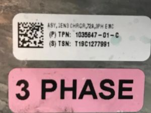
P/N 103564701C device is 3phase EU version of 72A output charger! On the outside you can distinguish it by a sticker on the side which says 3PH | P/N 103564701C device is 3phase EU version of 72A output charger! On the outside you can distinguish it by a sticker on the side which says 3PH | ||
[[File:Placard.jpg|thumb]] | |||
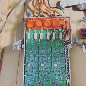
Charger with top cover removed | |||
[[File:74712D46-548E-4598-B4E9-78A7C2EE93E1.jpg|thumb]] | |||
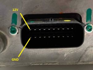
Step 1, to confirm all modules charger work you can connect 12V between top and bottom leftmost pins of the LV connector. Every modul lits its standby LED. | |||
[[File:S-l500.jpg|thumb]] | |||
Step 2, was to remove internal components from contactor box in front of the modules. There are DC rails, AC rails, fuse and contactors which we will not use. | |||
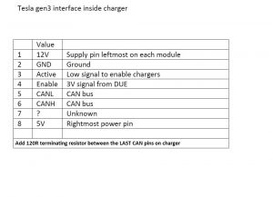
Step 3, i inspected each power modules contact points with control board. This is where i will apply my new wiring to be able to control the charger. | |||
[[File:Wiring of the internal module pins.jpg|thumb]] | |||
== gen 3 controller == | == gen 3 controller == | ||
Revision as of 05:29, 30 September 2022
The Tesla GEN3 is a single/three phase AC charger that was fitted in the Model S starting with the 2016 'facelift' model. The GEN3 has been fitted on all Model X models.
It is 566mm long, 360mm wide and 90mm high, without the water ports on both small sides. On the underside there are 8 M6 threads to attach.
P/N 103564701C device is 3phase EU version of 72A output charger! On the outside you can distinguish it by a sticker on the side which says 3PH
Charger with top cover removed
Step 1, to confirm all modules charger work you can connect 12V between top and bottom leftmost pins of the LV connector. Every modul lits its standby LED.
Step 2, was to remove internal components from contactor box in front of the modules. There are DC rails, AC rails, fuse and contactors which we will not use.
Step 3, i inspected each power modules contact points with control board. This is where i will apply my new wiring to be able to control the charger.


