Nissan Leaf Gen 3 (2018 up EM57): Difference between revisions
Jump to navigation
Jump to search
mNo edit summary |
(Adding to the Gen 3 leaf page) |
||
| Line 1: | Line 1: | ||
[[File:Leaf Gen.3.png|thumb]] | |||
== This adapter board is compatible with Gen 3 Nissan Leaf (model year 2018+) inverters and the [[Mini Mainboard|open inverter mini main board]]. == | |||
=== There are optional jumpers on both the adapter board and the mini mainboard. These must be set correctly before powering up or damage may result (if set for 3.3v and you apply 12v.) === | |||
=== These are: === | |||
<blockquote>**SJ1** (mini mainboard back) enables a 500 ohm pull-up resistor that is needed for open collector encoders. | |||
**SJ3** (mini mainboard) soldered to the left is setup for cruise control 12v input. Soldered to the right is 3.3v mosi for SPI communications. | |||
**SJ4** Leaf adapter board lower right side is a shorted jumper. This jumper allows disconnecting the brake output circuitry from the board address circuitry for testing (see Mini Mainboard Hardware Detection.) This line is shared between a board address and a brake light output. Once this is proven out there should be no need to change this jumper. | |||
**SJ5** Is an Emergency Stop (E-Stop) input to quickly, non-destructively, and safely shut down the inverter. To use an E-Stop function, cut the SJ5 jumper. To ignore the E-Stop functionality just leave the SJ5 jumper closed / shorted. | |||
**SJH1 & SJL1** connects the CAN high line to a resistor pair to provide a 120 ohm termination resistor if desired. These should be either both soldered or open only, not one open, one closed. There is a capacitor in the middle of the 2 60 ohm resistors to help filter noise on the CAN lines.</blockquote> | |||
[[File:Mini mainboard.png|thumb]] | |||
Revision as of 20:02, 21 October 2023
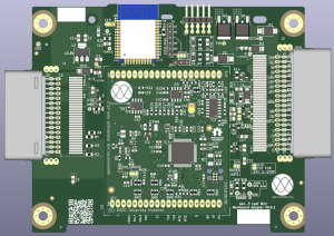
This adapter board is compatible with Gen 3 Nissan Leaf (model year 2018+) inverters and the open inverter mini main board.
There are optional jumpers on both the adapter board and the mini mainboard. These must be set correctly before powering up or damage may result (if set for 3.3v and you apply 12v.)
These are:
**SJ1** (mini mainboard back) enables a 500 ohm pull-up resistor that is needed for open collector encoders.
- SJ3** (mini mainboard) soldered to the left is setup for cruise control 12v input. Soldered to the right is 3.3v mosi for SPI communications.
- SJ4** Leaf adapter board lower right side is a shorted jumper. This jumper allows disconnecting the brake output circuitry from the board address circuitry for testing (see Mini Mainboard Hardware Detection.) This line is shared between a board address and a brake light output. Once this is proven out there should be no need to change this jumper.
- SJ5** Is an Emergency Stop (E-Stop) input to quickly, non-destructively, and safely shut down the inverter. To use an E-Stop function, cut the SJ5 jumper. To ignore the E-Stop functionality just leave the SJ5 jumper closed / shorted.
- SJH1 & SJL1** connects the CAN high line to a resistor pair to provide a 120 ohm termination resistor if desired. These should be either both soldered or open only, not one open, one closed. There is a capacitor in the middle of the 2 60 ohm resistors to help filter noise on the CAN lines.

