Renault Kangoo 36: Difference between revisions
m (Adding low voltage pin out) |
m (Adding extra details) |
||
| Line 1: | Line 1: | ||
[[Category:OEM]] | [[Category:OEM]] | ||
The phase 2 Renault Kangoo 36kWh pack consists of 12 modules, roughly 16kg 14x21x31 cm each. The usable capacity is apparently 33kWh. | The phase 2 Renault Kangoo 36kWh pack consists of 12 modules, roughly 16kg 14x21x31 cm each. The usable capacity is apparently 33kWh. It uses a centralised BMS, like the Nissan Leaf, as opposed to a distributed BMS with each module having it's own satellite board. So care must be taken to ensure the cell tap plugs are connected in to the modules in the correct order or the BMS may be damaged. '''Also note the cell taps will have potentially high voltage across them.''' | ||
==== Contactor Box ==== | |||
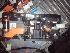
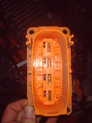
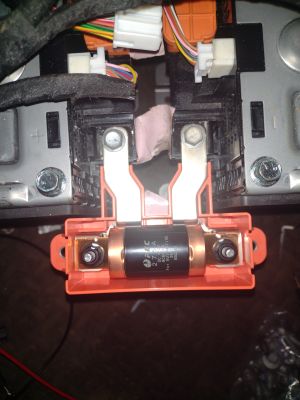
The pack doesn't have a negative contactor, the only way to isolate it is to pull the service disconnect. In the contactor box there's a current sensor, pre-charge resistor, pre-charge relay, main contactor and a 275a 1000V fuse. | |||
The main contactor is 150a rated. | |||
{| class="wikitable" | |||
|+ | |||
|[[File:Kangoo Contactor box.jpg|none|thumb]]Contactor box | |||
|[[File:Kangoo Disconnect.jpg|none|thumb]]Manual Service Disconnect socket | |||
|[[File:Kangoo Midpack Fuse.jpg|none|thumb]]Mid Pack Fuse | |||
|} | |||
There are 2 external Low voltage Connectors | |||
There are 2 external Low voltage Connectors for the battery pack. | |||
===== Grey Yazaki x ===== | ===== Grey Yazaki x ===== | ||
| Line 88: | Line 99: | ||
|Pre-charge relay (ground to close) | |Pre-charge relay (ground to close) | ||
|} | |} | ||
==== BMS ==== | |||
Revision as of 09:18, 1 February 2024
The phase 2 Renault Kangoo 36kWh pack consists of 12 modules, roughly 16kg 14x21x31 cm each. The usable capacity is apparently 33kWh. It uses a centralised BMS, like the Nissan Leaf, as opposed to a distributed BMS with each module having it's own satellite board. So care must be taken to ensure the cell tap plugs are connected in to the modules in the correct order or the BMS may be damaged. Also note the cell taps will have potentially high voltage across them.
Contactor Box
The pack doesn't have a negative contactor, the only way to isolate it is to pull the service disconnect. In the contactor box there's a current sensor, pre-charge resistor, pre-charge relay, main contactor and a 275a 1000V fuse.
The main contactor is 150a rated.
| Contactor box | Manual Service Disconnect socket | Mid Pack Fuse |
There are 2 external Low voltage Connectors for the battery pack.
Grey Yazaki x
| Pin | Internal Wire | Function |
|---|---|---|
| 1 | Black | 12v BMS supply via 10a fuse |
| 2 | x | |
| 3 | x | |
| 4 | x | |
| 5 | x | |
| 6 | Yellow | Can High |
| 7 | White | 12v Contactor supply via 15a fuse |
| 8 | x | |
| 9 | x | |
| 10 | x | |
| 11 | x | |
| 12 | Blue | Can Low |
Black Yazaki 7283-8854-30
| Pin | Internal Wire | Function |
|---|---|---|
| 1 | Black | Ground |
| 2 | x | |
| 3 | Green | Main Contactor (ground to close) |
| 4 | x | |
| 5 | Blue | Pre-charge relay (ground to close) |


