BMW i3 Inverter: Difference between revisions
(Updated with summary of fixes required to drop-in boards, link to forum post on parameters used for successful bench test, additional information on resolver adaptor boards, and list of remaining tasks to be resolved.) |
mNo edit summary |
||
| Line 366: | Line 366: | ||
|Unused | |Unused | ||
|} | |} | ||
'''Motor Resolver & Temperature Sensor Adaptor Boards''' | |||
'''Motor Resolver & Temperature Sensor Adaptor Boards''' | '''Motor Resolver & Temperature Sensor Adaptor Boards''' | ||
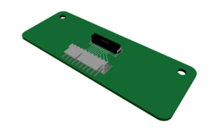
[[File:ERNI Microbridge adapter board.png|thumb|300x300px|ERNI Microbridge adapter board]] | [[File:ERNI Microbridge adapter board.png|thumb|300x300px|ERNI Microbridge adapter board]] | ||
[[File:Ampseal board.png|thumb|300x300px|Ampseal adapter board]] | [[File:Ampseal board.png|thumb|300x300px|Ampseal adapter board]] | ||
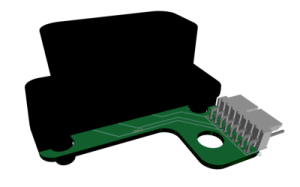
A pair of adaptor boards (see images to right) are available and shipped with the current drop-in boards. These enable the ERNI Microbridge connector from the resolver to be connected to the required pins on the Ampseal connector. Design files for these boards will be posted on github at some point - if you need a copy in the meantime contact user 'CJW' or post on the i3 controller hacking thread. | A pair of adaptor boards (see images to right) are available and shipped with the current drop-in boards. These enable the ERNI Microbridge connector from the resolver to be connected to the required pins on the Ampseal connector. Design files for these boards will be posted on github at some point - if you need a copy in the meantime contact user 'CJW' or post on the i3 controller hacking thread. | ||
'''Code Update for Gate Driver Board - SPI Commication''' | |||
'''Code Update for Gate Driver Board - SPI Commication''' | '''Code Update for Gate Driver Board - SPI Commication''' | ||
Revision as of 11:20, 12 April 2024
BMW I3 inverter
Forum thread: https://openinverter.org/forum/viewtopic.php?p=23214#p23214
BMW i3™ inverter drop-in board Available
https://openinverter.org/shop/index.php?route=product/product&product_id=72
Overview
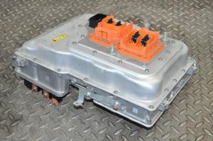
There are 2 variants of the i3, the standard i3 with motor power rated at 125kW and the i3s rated at 135kW.
There are 2 subvariants, as REX versions have an additional 25kw inverter and onboard generator.
Power stage: Infineon FS800R07 IGBTs rated for 800amps 650v
Openinverter Drop-in Board
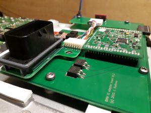
The drop-in board houses the openinverter, generates 32V for the gate driver board, communicates via SPI with the gate driver board to obtain voltage and temperature readouts, and provides outputs to operate contactors.
As of 12 April 2024, the following mods are required to use these boards:
- Check solder connections on the 40 pin surface mount Harwin connector to the gate driver board for dry joints or shorts
- Apply code update in section below to prevent err_out pin on openinverter interfering with SPI communications
- Pin 35 of the Harwin connector to the gate driver board is not connected to anything, but testing indicates this must be powered for the gate driver to work, at least on some boards. Voltage required at pin to be confirmed.
Pinouts for the three connectors on this board below.
| Pin No | Assigniment | Description |
|---|---|---|
| 1 | 12V | |
| 2 | BRAKE_IN | |
| 3 | PRECHARGE_OUT | |
| 4 | CANL | |
| 5 | CANH | |
| 6 | DCSW_OUT | |
| 7 | FORWARD_IN | |
| 8 | REVERSE_IN | |
| 9 | 5V (OUT) | |
| 10 | RESOLVER_S2/ENCODER_A | Sin Hi |
| 11 | GND | |
| 12 | RESOLVER_S1 | Sin Lo |
| 13 | THROTTLE1 | |
| 14 | THROTTLE2 | |
| 15 | RESOLVER_R1 | Ex Hi |
| 16 | RESOLVER_S3/ENCODER_B | Cos Hi |
| 17 | MTEMP+ | |
| 18 | MTEMP- | |
| 19 | RESOLVER_S4 | Cos Lo |
| 20 | EMCYSTOP_IN | |
| 21 | GND | |
| 22 | RESOLVER_R2 | Ex Lo |
| 23 | START_IN |
| Pin No | I/O | Description | Notes | Pin No | I/O | Description | Notes | |
|---|---|---|---|---|---|---|---|---|
| 1 | 21 | GND Switching Mosfets ? | ||||||
| 2 | I | 32V in | 22 | GND Switching Mosfets ? | ||||
| 3 | I | 32V in | 23 | |||||
| 4 | I | IGBT A HI | 24 | |||||
| 5 | I | IGBT A LOW | 25 | |||||
| 6 | I | CS (ADC) | 26 | GND IGBT Driver ground | ||||
| 7 | I | SDI | 27 | GND IGBT Driver ground | ||||
| 8 | I | SDO | 28 | GND IGBT Driver ground | ||||
| 9 | I | SCK | 29 | GND IGBT Driver ground | ||||
| 10 | I | IGBT B HI | 30 | GND IGBT Driver ground | ||||
| 11 | I | IGBT B LOW | 31 | GND IGBT Driver ground | ||||
| 12 | I | IGBT C HI | 32 | GND IGBT Driver ground | ||||
| 13 | I | IGBT C LOW | 33 | 5V IGBT Driver Power | ||||
| 14 | 34 | 5V IGBT Driver Power | ||||||
| 15 | 35 | I | IGBT PSU 12V on | |||||
| 16 | O | IGBT DRIVER UVW Upper Ready | 36 | O | IGBT Driver Fault | |||
| 17 | O | IGBT DRIVER UVW Lower Ready | 37 | I | 5V LEM Current sensor Power | |||
| 18 | O | Current Sense C Signal | 38 | GND Current sensor Ground | ||||
| 19 | O | Current Sense B Signal | 39 | GND Current sensor Ground | ||||
| 20 | O | Current Sense A Signal | 40 | GND Current sensor Ground |
Motor Resolver & Temperature Sensors
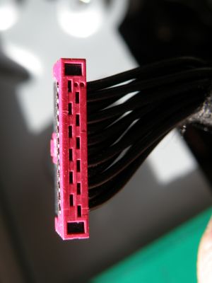
12-pin PCB header to connect to the motor sensors is an ERNI MiniBridge, part number 294920
Wire colours to pin allocation below determined by schematic and multimeter trace, with resolver coils and temperature sensors checked for resistance. Confirmed with motor bench test.
| Pin No | Colour | Description | Notes |
|---|---|---|---|
| 1 | Brown | Sin Hi | Twisted pair. 22.4 - 33.6 Ω. |
| 2 | Blue | Sin Lo | |
| 3 | Yellow | Ex Hi | Twisted pair. 22.4 - 33.6 Ω |
| 4 | Green | Ex Lo | |
| 5 | Red | Cos Hi | Twisted pair. 13.6 - 20.4 Ω |
| 6 | White | Cos Lo | |
| 7 | Blue | Temperature
Sensor |
From BMW Service Technical Training Manual - I01 High-voltage Components:
There are two stator coil temperature sensors. The rotor temperature is determined using readings from the stator temperature sensors. |
| 8 | Grey | ||
| 9 | Red | Temperature
Sensor | |
| 10 | Grey | ||
| 11 | - | Unused | These wires terminate in one of the six pin connectors in the motor housing. There is nothing connected to them. |
| 12 | - | Unused |
Motor Resolver & Temperature Sensor Adaptor Boards
Motor Resolver & Temperature Sensor Adaptor Boards
A pair of adaptor boards (see images to right) are available and shipped with the current drop-in boards. These enable the ERNI Microbridge connector from the resolver to be connected to the required pins on the Ampseal connector. Design files for these boards will be posted on github at some point - if you need a copy in the meantime contact user 'CJW' or post on the i3 controller hacking thread. Code Update for Gate Driver Board - SPI Commication
Code Update for Gate Driver Board - SPI Commication
The BMW i3 gate driver board communicates the DC bus voltage (ie traction battery voltage) and IGBT heatsink temperatures to the Openinverter via SPI.
On the Openinverter mini mainboard, pin 17 on JP2 is normally used as an 'Error Output'. When used with the BMW i3, this pin must instead be used for the SPI Clock signal.
To avoid the clock signal being pulled high or low by the pin acting as an Error Output, find this section of code in vehiclecontrol.cpp:
//Brake pin is used as SPI_MISO
DigIo::brk_out.Configure(GPIOC, GPIO5, PinMode::INPUT_FLT);
and insert these lines of code below it, to disable the Error Output:
//Disable err_out so it doesn't pull the clock signal up or down
DigIo::err_out.Configure(GPIOC, GPIO10, PinMode::INPUT_FLT);
Openinverter Parameters
As of 12 April 2024, page 10 of the forum thread contains an initial set of parameters that were successfully used for bench testing a motor with a pair of lead acid car batteries. Will update and eventually post a full set of parameters here once the motor is properly set up and has been tested with a high voltage battery.
Future Development
List of tasks to be completed to enable full use of these motors:
- Required voltage for pin 35 of Harwin gate driver board connector to be confirmed
- Motor temperature sensor to be mapped and added to code
- Design files for adaptor boards posted to github
