VW EGolf Battery: Difference between revisions
No edit summary |
m (Added some pictures) |
||
| (2 intermediate revisions by the same user not shown) | |||
| Line 1: | Line 1: | ||
== Versions == | |||
* Gen1 2014 -2017 24.2 kWh Panasonic cells | |||
* Gen2 2017-onwards 35.8 kWh Samsung cells | |||
== Overview == | |||
[[File:2020 e-Golf Battery pack.jpg|thumb|2020 e-Golf Battery pack]] | |||
Packs are 88 cells in series making a nominal pack voltage of 325v (3.7v per cell). | |||
== Gen2 Battery pack == | |||
The pack consists of: | The pack consists of: | ||
| Line 36: | Line 17: | ||
10 half slave modules (2s3p) | 10 half slave modules (2s3p) | ||
Every master module communicates over CAN (500 kbs) and the most important bits has been backwards engineered by the champs in this | Total pack is 88s3p. Each cell is 37 Ah, 3.7 V, each cell cluster 37*3=111 Ah. The pack interconnections is of 35 mm^2 copper busbars, both stiff and flexible mixed. The chemistry of the cells is NCM111 or NCM333. | ||
Every master module communicates over CAN (500 kbs) and the most important bits has been backwards engineered by the champs in this forum (kudos to them!). Every master module consumes about 30 mA when awake and powered from 12V. | |||
This is what can be read and controlled over CAN: | This is what can be read and controlled over CAN: | ||
| Line 46: | Line 28: | ||
- Read temperature of every module, 1 sensor per module. Accuracy 0.5 degC | - Read temperature of every module, 1 sensor per module. Accuracy 0.5 degC | ||
- Read balancing status for every cell | - Read balancing status for every cell (on/off) | ||
- Control balancing on/off for every cell (on/off) | |||
The master modules seems to be very resistant against malconnections. I have not broken any masters, even though I messed up the connections many times. At some times, I have felt heat purge through the cover of the PCB when I messed up some blue connectors, but they seem to not take damage. So don't worry too much.... ;) | |||
=== Dismantling === | |||
'''!!! SAFETY WARNING !!!''' | |||
The | '''The contactor/precharge circuit has a charged capacitor bank inside the battery pack.''' '''This must be bled manually using external resistor at disassembly.''' | ||
'''''Proceed with cation during pack disassembly!''''' | |||
[[File:2020 e-Golf Battery pack without cover.jpg|thumb|2020 e-Golf battery pack with protective cover removed.]] | |||
There are just a few screws and nuts holding the cover in place. Then pry around the edge all around too remove the glue holding it in place. There are several videos on Youtube walking through the process. | |||
=== Wiring === | |||
The modules are connected with busbars. These are probably of least interest as these might be hard to reuse later given their unique shapes. | The modules are connected with busbars. These are probably of least interest as these might be hard to reuse later given their unique shapes. | ||
In the pack you'll find two main cables harnesses, one orange and one black. | In the pack you'll find two main cables harnesses, one orange and one black. | ||
Black = 12V cabling, U30, Ignition, CAN H, CAN L etc. Connects all master modules | * Black = 12V cabling, U30, Ignition, CAN H, CAN L etc. Connects all master modules | ||
* Orange = Balancing leads between slaves and masters + temperature leads of the slaves | |||
Orange = Balancing leads between slaves and masters + temperature leads of the slaves | |||
The orange cabling is actually 8 separate harnesses. First thing is to unwrap most of the orange tape to find the 8 separate smaller harnesses. | The orange cabling is actually 8 separate harnesses. First thing is to unwrap most of the orange tape to find the 8 separate smaller harnesses. | ||
| Line 76: | Line 63: | ||
- Two, three or four blue connectors = Balancing leads and temperature leads from slaves. More on this later... | - Two, three or four blue connectors = Balancing leads and temperature leads from slaves. More on this later... | ||
Note that the orange harnesses is all different and must be matched with the correct master module. More on that later. | |||
=== Module configuration === | |||
[[File:Module PCBs.jpg|thumb|Master and slave module without protective top cover on]] | |||
Every master modules is uniquely configured for a set of either full of half slave connections. | Every master modules is uniquely configured for a set of either full of half slave connections. | ||
"2" means half-slave 2S3P | |||
"4" means fill-slave 4S3P | |||
CMC6 = 4 + 4 | * CMC1 = 2 + 2 + 2 + 2 | ||
* CMC2 = 4 + 2 + 2 | |||
CMC7 = 4 + 4 | * CMC3 = 2 + 2 | ||
* CMC4 = 4 + 2 | |||
CMC8 = 4 + 2 | * CMC5 = 4 + 4 | ||
* CMC6 = 4 + 4 | |||
* CMC7 = 4 + 4 | |||
* CMC8 = 4 + 2 | |||
Note: CMC 5/6/7 and CMC 4/8 share the same configuration, therefore, the orange cable harness is interchangeable between those. | Note: CMC 5/6/7 and CMC 4/8 share the same configuration, therefore, the orange cable harness is interchangeable between those. | ||
| Line 108: | Line 90: | ||
The orange cable harness with 4 blue connectors goes to CMC1. | The orange cable harness with 4 blue connectors goes to CMC1. | ||
* The only CMC with 4 slaves | |||
* Slave #1 blue connector with one of the cables yellow | |||
* Slave #2 blue connector with one of the cables red | |||
* Slave #3 blue connector with one of the cables purple | |||
* Slave #4 blue connector with one of the cables green | |||
The orange cable harness with 3 blue connectors goes to CMC2. | The orange cable harness with 3 blue connectors goes to CMC2. | ||
* The only CMC with 3 slaves | |||
* Slave #1 blue connector with one of the cables yellow | |||
* Slave #2 blue connector with one of the cables purple | |||
* Slave #3 blue connector with one of the cables green | |||
For the rest of the cable harnesses with only 2 blue connectors, it's a bit more tricky. As it happens, slave #1 will always have the blue connector with the yellow cable (among others, but let's focus on the yellow). If the blue connector with the yellow cable has: | For the rest of the cable harnesses with only 2 blue connectors, it's a bit more tricky. As it happens, slave #1 will always have the blue connector with the yellow cable (among others, but let's focus on the yellow). If the blue connector with the yellow cable has: | ||
* 4 cables in total, the first slave is a half module. This means the cable harness is for CMC3. | |||
* 6 cables in total, the first slave is a full module This means CMC 4/5/6/7/8 | |||
If the other connector than the one with a yellow cable has: | If the other connector than the one with a yellow cable has: | ||
* 4 cables, then its for CMC 4 and 8 | |||
* 6 cables, then its for CMC 5, 6 and 7 | |||
=== Connecting to the master modules on CAN === | |||
In order to make the master modules behave "nicely" and send and respond on CAN as expected, they need all prerequisites fulfilled: | In order to make the master modules behave "nicely" and send and respond on CAN as expected, they need all prerequisites fulfilled: | ||
* The right orange cable to the right amount of slaves and the right type of slave (as per above). | |||
* All brown wires from the black connector to GND | |||
* All green and red, green and yellow wires from the black connector to +12V (TO BE CONFIRMED) | |||
* Master (+) terminal connected to Slave 1 (-) | |||
* Slave 1 (+) connected to Slave 2 (-) and so on... | |||
The cell temperature and balancing status is reported continuously. | The cell temperature and balancing status is reported continuously. | ||
| Line 162: | Line 126: | ||
The cell voltages are only transmitted as response to a message: | The cell voltages are only transmitted as response to a message: | ||
CAN standard: 0xBA: | |||
*Byte 0: 0x45 | |||
*Byte 1: 0x1 | |||
* Byte 2: 0x28 | |||
* Byte 3: 0x0 | |||
* Byte 4: 0x0 | |||
* Byte 5: 0x0 | |||
* Byte 6: 0x0 | |||
* Byte 7: 0x30 | |||
For testing, I've been using CANKing. Works well enough and has the functionality needed for this. | For testing, I've been using CANKing. Works well enough and has the functionality needed for this. | ||
Latest revision as of 06:47, 30 August 2024
Versions
- Gen1 2014 -2017 24.2 kWh Panasonic cells
- Gen2 2017-onwards 35.8 kWh Samsung cells
Overview
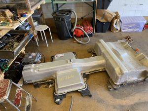
Packs are 88 cells in series making a nominal pack voltage of 325v (3.7v per cell).
Gen2 Battery pack
The pack consists of:
8 master modules (4s3p)
9 full slave modules (4s3p)
10 half slave modules (2s3p)
Total pack is 88s3p. Each cell is 37 Ah, 3.7 V, each cell cluster 37*3=111 Ah. The pack interconnections is of 35 mm^2 copper busbars, both stiff and flexible mixed. The chemistry of the cells is NCM111 or NCM333.
Every master module communicates over CAN (500 kbs) and the most important bits has been backwards engineered by the champs in this forum (kudos to them!). Every master module consumes about 30 mA when awake and powered from 12V.
This is what can be read and controlled over CAN:
- Read every cell voltage, accuracy 1 mV
- Read temperature of every module, 1 sensor per module. Accuracy 0.5 degC
- Read balancing status for every cell (on/off)
- Control balancing on/off for every cell (on/off)
The master modules seems to be very resistant against malconnections. I have not broken any masters, even though I messed up the connections many times. At some times, I have felt heat purge through the cover of the PCB when I messed up some blue connectors, but they seem to not take damage. So don't worry too much.... ;)
Dismantling
!!! SAFETY WARNING !!!
The contactor/precharge circuit has a charged capacitor bank inside the battery pack. This must be bled manually using external resistor at disassembly.
Proceed with cation during pack disassembly!
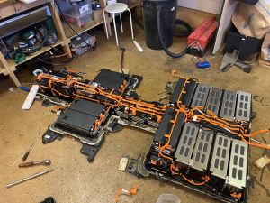
There are just a few screws and nuts holding the cover in place. Then pry around the edge all around too remove the glue holding it in place. There are several videos on Youtube walking through the process.
Wiring
The modules are connected with busbars. These are probably of least interest as these might be hard to reuse later given their unique shapes.
In the pack you'll find two main cables harnesses, one orange and one black.
- Black = 12V cabling, U30, Ignition, CAN H, CAN L etc. Connects all master modules
- Orange = Balancing leads between slaves and masters + temperature leads of the slaves
The orange cabling is actually 8 separate harnesses. First thing is to unwrap most of the orange tape to find the 8 separate smaller harnesses.
Each harness has:
- One black connector = Temperature leads to the master
- One red connector = Balancing leads to master
- Two, three or four blue connectors = Balancing leads and temperature leads from slaves. More on this later...
Note that the orange harnesses is all different and must be matched with the correct master module. More on that later.
Module configuration
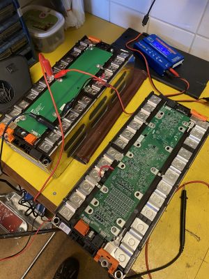
Every master modules is uniquely configured for a set of either full of half slave connections.
"2" means half-slave 2S3P
"4" means fill-slave 4S3P
- CMC1 = 2 + 2 + 2 + 2
- CMC2 = 4 + 2 + 2
- CMC3 = 2 + 2
- CMC4 = 4 + 2
- CMC5 = 4 + 4
- CMC6 = 4 + 4
- CMC7 = 4 + 4
- CMC8 = 4 + 2
Note: CMC 5/6/7 and CMC 4/8 share the same configuration, therefore, the orange cable harness is interchangeable between those.
The master is always the most negative. From the positive pole of the master, the first slave's negative connects, and so on.
(-) Master (+)(-) Slave #1 (+)(-) Slave #2 (+)(-) Slave #3 (+)(-) Slave #4 (+)
The orange cable harness with 4 blue connectors goes to CMC1.
- The only CMC with 4 slaves
- Slave #1 blue connector with one of the cables yellow
- Slave #2 blue connector with one of the cables red
- Slave #3 blue connector with one of the cables purple
- Slave #4 blue connector with one of the cables green
The orange cable harness with 3 blue connectors goes to CMC2.
- The only CMC with 3 slaves
- Slave #1 blue connector with one of the cables yellow
- Slave #2 blue connector with one of the cables purple
- Slave #3 blue connector with one of the cables green
For the rest of the cable harnesses with only 2 blue connectors, it's a bit more tricky. As it happens, slave #1 will always have the blue connector with the yellow cable (among others, but let's focus on the yellow). If the blue connector with the yellow cable has:
- 4 cables in total, the first slave is a half module. This means the cable harness is for CMC3.
- 6 cables in total, the first slave is a full module This means CMC 4/5/6/7/8
If the other connector than the one with a yellow cable has:
- 4 cables, then its for CMC 4 and 8
- 6 cables, then its for CMC 5, 6 and 7
Connecting to the master modules on CAN
In order to make the master modules behave "nicely" and send and respond on CAN as expected, they need all prerequisites fulfilled:
- The right orange cable to the right amount of slaves and the right type of slave (as per above).
- All brown wires from the black connector to GND
- All green and red, green and yellow wires from the black connector to +12V (TO BE CONFIRMED)
- Master (+) terminal connected to Slave 1 (-)
- Slave 1 (+) connected to Slave 2 (-) and so on...
The cell temperature and balancing status is reported continuously.
The cell voltages are only transmitted as response to a message:
CAN standard: 0xBA:
- Byte 0: 0x45
- Byte 1: 0x1
- Byte 2: 0x28
- Byte 3: 0x0
- Byte 4: 0x0
- Byte 5: 0x0
- Byte 6: 0x0
- Byte 7: 0x30
For testing, I've been using CANKing. Works well enough and has the functionality needed for this.
All CAN communications are documented in this DBC file. This file is based on the works of Tom-evnut, but complemented and cleaned up by me.
https://github.com/haand22/VW-e-Golf.git


