Nissan leaf: Difference between revisions
Scrappyjoe (talk | contribs) Add link to CANBUS db github repo |
No edit summary |
||
| (2 intermediate revisions by 2 users not shown) | |||
| Line 1: | Line 1: | ||
[[File:0000628 blogimages-1.jpg|thumb]] | [[File:0000628 blogimages-1.jpg|thumb]] | ||
This unit takes the 280-400VDC HV battery pack input and converts it to 13-15VDC for the 12V AUX battery charging. It is very stable at 74 Amps 13.6V output. Easily adjustable voltage output with a simple 10V [[wikipedia:Pulse-width_modulation|PWM]] signal running at about 9 HZ on pin 1 and pin 3 and 11 go to +12V to enable. | This DCDC unit takes the 280-400VDC HV battery pack input and converts it to 13-15VDC for the 12V AUX battery charging. It is very stable at 74 Amps 13.6V output. Easily adjustable voltage output with a simple 10V [[wikipedia:Pulse-width_modulation|PWM]] signal running at about 9 HZ on pin 1 and pin 3 and 11 go to +12V to enable. | ||
When i googled around i noticed this particular DCDC is documented on various sites and videos, however not with schematics or wiring diagrams… | When i googled around i noticed this particular DCDC is documented on various sites and videos, however not with schematics or wiring diagrams… | ||
| Line 15: | Line 15: | ||
Well it was all good and well with the wiring obtained online, however i noticed that DCDC starts as soon as i provide 12V to pins 3 and 11 of connector and provides 14V power to charge 12V battery. | Well it was all good and well with the wiring obtained online, however i noticed that DCDC starts as soon as i provide 12V to pins 3 and 11 of connector and provides 14V power to charge 12V battery. | ||
When i added 9Hz PWM to pin 1 of connector F11 i got following result: | When i added 9Hz PWM to pin 1 of connector F11 i got following result:<br> | ||
PWM voltage | PWM voltage<br> | ||
80% 13,10V | 80% 13,10V<br> | ||
70% 13,40V | 70% 13,40V<br> | ||
60% 13,70V | 60% 13,70V<br> | ||
50% 14,00V | 50% 14,00V<br> | ||
40% 14,30V | 40% 14,30V<br> | ||
30% 14,70V | 30% 14,70V<br> | ||
20% 15,00V | 20% 15,00V<br> | ||
If i remove PWM from pin 1 i again get 14V on DCDC output. | If i remove PWM from pin 1 i again get 14V on DCDC output. | ||
| Line 33: | Line 34: | ||
A database of Nissan Leaf CAN Bus messages can be found here https://github.com/dalathegreat/leaf_can_bus_messages | A database of Nissan Leaf CAN Bus messages can be found here https://github.com/dalathegreat/leaf_can_bus_messages | ||
[[Category:Nissan]] | |||
Latest revision as of 20:13, 31 August 2024

This DCDC unit takes the 280-400VDC HV battery pack input and converts it to 13-15VDC for the 12V AUX battery charging. It is very stable at 74 Amps 13.6V output. Easily adjustable voltage output with a simple 10V PWM signal running at about 9 HZ on pin 1 and pin 3 and 11 go to +12V to enable.
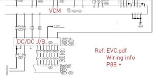
When i googled around i noticed this particular DCDC is documented on various sites and videos, however not with schematics or wiring diagrams… I used some photos and wiring from here: http://myimiev.com/forum/viewtopic.php?t=4533 Starting with connection of the 12v positive terminal to battery And then GND the case back to battery negative terminal I connected HV directly to DCDC input wires.


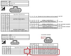
Then referring to plugs F11 & F12 Terminal 3 and 11 would need +12v for Battery power supply Pin 1 needs a PWM signal 9Hz 50% duty to it
Well it was all good and well with the wiring obtained online, however i noticed that DCDC starts as soon as i provide 12V to pins 3 and 11 of connector and provides 14V power to charge 12V battery.
When i added 9Hz PWM to pin 1 of connector F11 i got following result:
PWM voltage
80% 13,10V
70% 13,40V
60% 13,70V
50% 14,00V
40% 14,30V
30% 14,70V
20% 15,00V
If i remove PWM from pin 1 i again get 14V on DCDC output.
Also i tested the output with 14V 85A load (9x H4 light bulbs and 60Ah Pb battery) and DCDC provided true and steady 14V power.
CAN bus messages
A database of Nissan Leaf CAN Bus messages can be found here https://github.com/dalathegreat/leaf_can_bus_messages