Chademo with Zombieverter: Difference between revisions
Jump to navigation
Jump to search
No edit summary |
mNo edit summary |
||
| (2 intermediate revisions by 2 users not shown) | |||
| Line 6: | Line 6: | ||
* 2 Contactors for Chademo use | * 2 Contactors for Chademo use | ||
* Zombie VCU | * Zombie VCU | ||
* Jumper settings as per the instructions on the back of the board. | * Jumper settings for HS CAN3. Solder SJ6, SJ7, SJ8 and SJ9, as per the instructions on the back of the board. Additionally Solder SJ5 and SJ10 for CAN3 Termination. | ||
<gallery> | |||
File:ChademoJumpers.jpg | |||
</gallery> | |||
* Chademo set to Charge Control interface in the UI | * Chademo set to Charge Control interface in the UI | ||
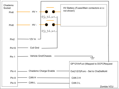
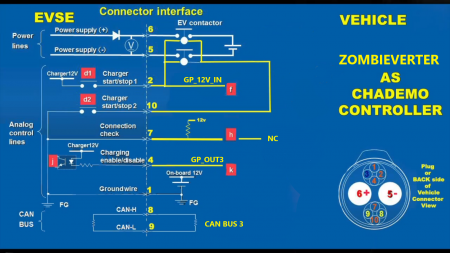
* An output set to ChaDeMoAl | * An output set to ChaDeMoAl | ||
* GP12VINFuct set to DCFCRequest in the UI | * GP12VINFuct set to DCFCRequest in the UI | ||
[[File:Zombie Chademo (2).png|thumb]] | [[File:Zombie Chademo (2).png|thumb|409x409px]] | ||
[[File:Z Chad2.png|alt=Chademo Zombieverter connection diagram|left|thumb|450x450px]] | [[File:Z Chad2.png|alt=Chademo Zombieverter connection diagram|left|thumb|450x450px]] | ||
[[Category:ZombieVerter]] | |||
[[Category:ChaDeMo]] | |||
[[Category: | |||
Latest revision as of 22:04, 9 February 2025
https://www.youtube.com/watch?v=zuPvgzQt6XQ
Requirements
- Chademo Socket
- 2 Contactors for Chademo use
- Zombie VCU
- Jumper settings for HS CAN3. Solder SJ6, SJ7, SJ8 and SJ9, as per the instructions on the back of the board. Additionally Solder SJ5 and SJ10 for CAN3 Termination.
- Chademo set to Charge Control interface in the UI
- An output set to ChaDeMoAl
- GP12VINFuct set to DCFCRequest in the UI


