Tesla Model S/X GEN3 Charger: Difference between revisions
Kevin Sharpe (talk | contribs) No edit summary |
|||
| (14 intermediate revisions by 6 users not shown) | |||
| Line 1: | Line 1: | ||
The Tesla GEN3 is a single/three phase AC charger that was fitted in the Model S starting with the 2016 'facelift' model. The GEN3 has been fitted on all Model X models. | The Tesla GEN3 is a single/three phase AC charger that was fitted in the Model S starting with the 2016 'facelift' model. The GEN3 has been fitted on all Model X models. | ||
It is 566mm long, 360mm wide and 90mm high, without the water ports on both small sides. On the underside there are 8 M6 threads to attach. | |||
"[https://openinverter.org/forum/viewtopic.php?f=10&t=78&p=9994#p9994 Running a Tesla charger at much under 200v dc will cause it to explode. Yes I know the label says 50 to 450v but it lies. Yes I blew one up discovering this.]" | "[https://openinverter.org/forum/viewtopic.php?f=10&t=78&p=9994#p9994 Running a Tesla charger at much under 200v dc will cause it to explode. Yes I know the label says 50 to 450v but it lies. Yes I blew one up discovering this.]" | ||
P/N 103564701C device is 3phase EU version of 72A output charger! On the outside you can distinguish it by a sticker on the side which says 3PH | |||
[[File:Placard.jpg|thumb]] | |||
Charger with top cover removed | |||
[[File:74712D46-548E-4598-B4E9-78A7C2EE93E1.jpg|thumb]] | |||
Step 1, to confirm all modules charger work you can connect 12V between top and bottom leftmost pins of the LV connector. Every modul lits its standby LED. | |||
Step 2, was to remove internal components from contactor box in front of the modules. There are DC rails, AC rails, fuse and contactors which we will not use. | |||
[[File:Pinout V1.jpg|thumb|Image from Damiens github repo to clarify pin no 1]] | |||
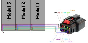
Step 3, inspect each power modules contact points with control board. This is where we will apply new wiring to be able to control the charger. See wiring table of module pinout. | |||
[[File:Wiring of the internal module pins.jpg|thumb]] | |||
[[File:Tesla Gen 3 Charger Pinout.jpg|thumb]] | |||
== gen 3 controller == | |||
https://github.com/damienmaguire/Tesla-Gen3-Charger | |||
== Low Voltage Connections == | |||
20 Way plug p/n :33472-2001 | |||
12 Way plug p/n:33472-1236 | |||
Pin p/n:33012-2002 20 way | |||
plug pinout (To Vehicle) | |||
{| class="wikitable" | |||
!Pin | |||
!Signal | |||
!Pin | |||
!Signal | |||
|- | |||
|1 | |||
|Ground | |||
|11 | |||
|CAN Ground | |||
|- | |||
|2 | |||
|12V Perm Supply | |||
|12 | |||
|USB D+ | |||
|- | |||
|3 | |||
|Output 1 | |||
|13 | |||
|USB D- | |||
|- | |||
|4 | |||
|Output 2 | |||
|14 | |||
|USB 5V | |||
|- | |||
|5 | |||
|Input 1 | |||
|15 | |||
|''Not Used'' | |||
|- | |||
|6 | |||
|Input 2 | |||
|16 | |||
|''Not Used'' | |||
|- | |||
|7 | |||
|EVSE Control Pilot (CP) | |||
|17 | |||
|''Not Used'' | |||
|- | |||
|8 | |||
|EVSE Proximity (PP) | |||
|18 | |||
|''Not Used'' | |||
|- | |||
|9 | |||
|CAN Low | |||
|19 | |||
|''Not Used'' | |||
|- | |||
|10 | |||
|CAN High | |||
|20 | |||
|''Not Used'' | |||
|} | |||
12 way plug pinout (To charger power modules) | |||
{| class="wikitable" | |||
!Pin | |||
!Signal | |||
!Pin | |||
!Signal | |||
|- | |||
|1 | |||
|Ground | |||
|7 | |||
|Charger 2 Activate Signal | |||
|- | |||
|2 | |||
|12V out | |||
|8 | |||
|Charger 3 Activate Signal | |||
|- | |||
|3 | |||
|5V out | |||
|9 | |||
|Charger 1 Enable Signal | |||
|- | |||
|4 | |||
|CAN Low | |||
|10 | |||
|Charger 2 Enable Signal | |||
|- | |||
|5 | |||
|CAN High | |||
|11 | |||
|Charger 3 Enable Signal | |||
|- | |||
|6 | |||
|Charger 1 Activate Signal | |||
|12 | |||
|''Not Used'' | |||
|} | |||
The "vehicle side" connector has digital inputs and outputs, these function the same as the Gen2 inputs and outputs: | |||
{| class="wikitable" | |||
|+ | |||
!Pin | |||
!Signal | |||
!Gen2 Name | |||
|- | |||
|3 | |||
|Output 1 | |||
|OUT1 - HV enable | |||
|- | |||
|4 | |||
|Output 2 | |||
|OUT2 - AC present | |||
|- | |||
|5 | |||
|Input 1 | |||
|input "D1" enable | |||
|- | |||
|6 | |||
|Input 2 | |||
| | |||
|} | |||
The other connections are named the same or have clearly identifiable functions. | |||
The outputs will not output 12v, they are low side switches. If you require a 12v ac present signal then use a relay with its coil switched from the relevant pin. | |||
== Software == | |||
Software is the same as the Gen2 Tesla Charge V5 boards | |||
[[Tesla Model S/Tesla Gen23 V5 Software]] | |||
[[Category:Tesla]] [[Category:Charger]] | |||
Latest revision as of 13:29, 15 February 2025
The Tesla GEN3 is a single/three phase AC charger that was fitted in the Model S starting with the 2016 'facelift' model. The GEN3 has been fitted on all Model X models.
It is 566mm long, 360mm wide and 90mm high, without the water ports on both small sides. On the underside there are 8 M6 threads to attach.
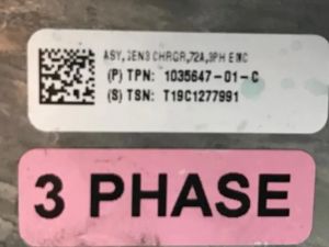
P/N 103564701C device is 3phase EU version of 72A output charger! On the outside you can distinguish it by a sticker on the side which says 3PH
Charger with top cover removed
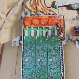
Step 1, to confirm all modules charger work you can connect 12V between top and bottom leftmost pins of the LV connector. Every modul lits its standby LED.
Step 2, was to remove internal components from contactor box in front of the modules. There are DC rails, AC rails, fuse and contactors which we will not use.
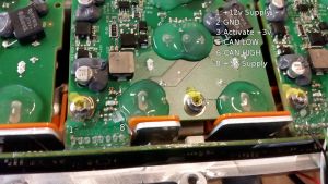
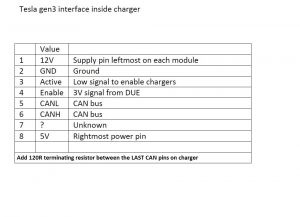
Step 3, inspect each power modules contact points with control board. This is where we will apply new wiring to be able to control the charger. See wiring table of module pinout.
gen 3 controller
https://github.com/damienmaguire/Tesla-Gen3-Charger
Low Voltage Connections
20 Way plug p/n :33472-2001
12 Way plug p/n:33472-1236
Pin p/n:33012-2002 20 way
plug pinout (To Vehicle)
| Pin | Signal | Pin | Signal |
|---|---|---|---|
| 1 | Ground | 11 | CAN Ground |
| 2 | 12V Perm Supply | 12 | USB D+ |
| 3 | Output 1 | 13 | USB D- |
| 4 | Output 2 | 14 | USB 5V |
| 5 | Input 1 | 15 | Not Used |
| 6 | Input 2 | 16 | Not Used |
| 7 | EVSE Control Pilot (CP) | 17 | Not Used |
| 8 | EVSE Proximity (PP) | 18 | Not Used |
| 9 | CAN Low | 19 | Not Used |
| 10 | CAN High | 20 | Not Used |
12 way plug pinout (To charger power modules)
| Pin | Signal | Pin | Signal |
|---|---|---|---|
| 1 | Ground | 7 | Charger 2 Activate Signal |
| 2 | 12V out | 8 | Charger 3 Activate Signal |
| 3 | 5V out | 9 | Charger 1 Enable Signal |
| 4 | CAN Low | 10 | Charger 2 Enable Signal |
| 5 | CAN High | 11 | Charger 3 Enable Signal |
| 6 | Charger 1 Activate Signal | 12 | Not Used |
The "vehicle side" connector has digital inputs and outputs, these function the same as the Gen2 inputs and outputs:
| Pin | Signal | Gen2 Name |
|---|---|---|
| 3 | Output 1 | OUT1 - HV enable |
| 4 | Output 2 | OUT2 - AC present |
| 5 | Input 1 | input "D1" enable |
| 6 | Input 2 |
The other connections are named the same or have clearly identifiable functions.
The outputs will not output 12v, they are low side switches. If you require a 12v ac present signal then use a relay with its coil switched from the relevant pin.
Software
Software is the same as the Gen2 Tesla Charge V5 boards