Lexus GS450h Drivetrain: Difference between revisions
(→Transmission: It is no longer believed that Toyota clutches have this input shaft as it is now confirmed.) |
|||
| (81 intermediate revisions by 16 users not shown) | |||
| Line 1: | Line 1: | ||
== Inverter == | |||
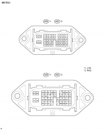
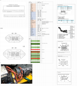
[[File:Inverter connector.png|thumb|GS450h inverter external connector|187x187px]] | [[File:Inverter connector.png|thumb|GS450h inverter external connector|187x187px]] | ||
The Lexus GS450h is a hybrid vehicle. Their inverters are suitable and attractive for DIY EVs because of: | The Lexus GS450h is a hybrid vehicle. Their inverters are suitable and attractive for DIY EVs because of: | ||
| Line 16: | Line 9: | ||
* Ease of repurposing. Emulating the original ECU seems reasonably feasible. The transmission is a similar size and layout to many RWD transmissions. | * Ease of repurposing. Emulating the original ECU seems reasonably feasible. The transmission is a similar size and layout to many RWD transmissions. | ||
The Lexus GS450h (2006-2012 model years) has a variety of useful components inside the inverter package: | The Lexus GS450h (2006-2012 model years) has a variety of useful components inside the inverter package: | ||
* Two high power inverters, for the 2 motors MG1 capable of handling | * Two high power inverters, for the 2 motors MG1 capable of handling >430 Amps, and MG2 capable of handling >215 Amps. <ref>https://toyota-club.net/files/faq/21-12-01_faq_hybrid_tr_en.htm</ref><ref>https://www.osti.gov/biblio/947393<nowiki/>see p. 62 for locked rotor test. 430A needed for 300Nm of MG2 torque, which is the official published value for the LS600h. (interestingly gs450h published value is 275Nm, although the two should share the same MG units and inverter). | ||
MG1 could possibly handle just as much, since copper amount is similar. But the inverter has half as many IGBTs for MG1 as MG2, so the current at system level is possibly halved.</ref> | |||
* A boost module to boost the 288v battery pack up to 650v as used in the Lexus (Note that voltages this high are not required for EV conversions). | * A boost module to boost the 288v battery pack up to 650v as used in the Lexus (Note that voltages this high are not required for EV conversions). | ||
For technical analysis of this unit, see pages 14-47 of this document: < | For technical analysis of this unit, see pages 14-47 of this document: <ref name=":0">https://www.osti.gov/servlets/purl/928684</ref> | ||
If you combine a LHD transmission with a RHD inverter (or vice versa) you might end up with a motor that is juddering, not spinning. IN this case you need to swap any two phase cables of both MG1 and MG2. | |||
'''<u>Note that even | The inverter is capable of running at full speeds on pack voltages from approx. 280V upwards. The maximum allowable input voltage is 650V, so far, many have found that "standard" EV voltages of 300V-360V to be well suited. | ||
'''<u>Note that even though the inverter maximum voltage rating is 650V, a 650V battery pack is not required to run this unit. It is capable of excellent performance at lower voltages, such as the typical 300V-360V found in most EVs. However, there is the opportunity to use larger packs with this unit if required in your application.</u>''' | |||
Should a higher voltage pack be chosen in your application for any reason, the buck/boost converter can be used to power auxiliary equipment at its native voltage. | Should a higher voltage pack be chosen in your application for any reason, the buck/boost converter can be used to power auxiliary equipment at its native voltage. | ||
Weight: 40 | Weight: 40 lbs | ||
Dimensions: 14" x 9-1/2" x 8-1/2" | Dimensions: 14" x 9-1/2" x 8-1/2" | ||
== | |||
A buck/boost converter lives within the inverter housing, originally this is used to step up the 288V battery pack in the GS450h to the 650V for use in the inverter in the GS. (Note that this does not mean the inverter requires 650V to run, it is simply a maximum rating) For those using a 600+V battery pack, this converter can be used to step the voltage down to a more reasonable level to interface with | ''Note: If using Zombieverter, the inverter needs powering up after Zombie, use Zombie to power up the inverter.'' | ||
=== Buck/Boost Converter === | |||
A buck/boost converter lives within the inverter housing, originally this is used to step up the 288V battery pack in the GS450h to the 650V for use in the inverter in the GS. (Note that this does not mean the inverter requires 650V to run, it is simply a maximum rating) For those using a 600+V battery pack, this converter can be used to step the voltage down to a more reasonable level to interface with chargers, DCDC converters, heaters, AC compressors, and other components which can be found in "regular" EV's (Tesla, LEAF, Volt, etc.). | |||
This unit is rated at 30kW, making it unsuitable for traction power, but good for auxiliary devices. | This unit is rated at 30kW, making it unsuitable for traction power, but good for auxiliary devices. | ||
| Line 38: | Line 38: | ||
Details on how to control the converter are here: https://openinverter.org/forum/viewtopic.php?f=14&t=538 | Details on how to control the converter are here: https://openinverter.org/forum/viewtopic.php?f=14&t=538 | ||
For technical analysis of this unit, see pages 14-47 of this document: < | For technical analysis of this unit, see pages 14-47 of this document: <ref name=":0" /> | ||
'''Do not connect your HV battery to the OEM battery location, for conversion you have to bypass the buck/boost converter and connect directly to the HV bus. See the 3D printable parts below to help with this.''' | |||
== Transmission == | |||
[[File:Inverter.png|thumb|213x213px|GS450h inverter and transmission pinout]] | |||
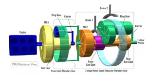
[[File:Transmission Layout.png|thumb|GS450h transmission layout]] | |||
For technical analysis of this transmission, see pages 46 and onward of this document:<ref name=":2">https://www.osti.gov/servlets/purl/947393 </ref> | |||
Motor information and ratios are as follows: | |||
MG1 speed is -2.29:1<ref name=":3">[https://slideplayer.com/slide/14432904/]</ref> | |||
MG1 <u>rated speed is not known at this time and recommended to stick to the same speed as MG2</u> | |||
MG2 speed can be 1.9:1 or 3.9:1<ref name=":3" /> | |||
MG2 is rated at 300Nm and max 10,230 rpm<ref name=":2" /> | |||
The transmission contains two "Motor-Generator" units. MG1 sits at the front of the transmission, and interfaces with the internal combustion engine through a planetary gear set. For this reason, to obtain torque from MG1, the input shaft of the transmission must be locked in place. This is usually done using a splined coupler, which is then welded onto the transmission front mount. | |||
The input shaft | The input shaft on the transmission has 21 splines, with a 28mm major diameter. There are several Toyota clutches which have this in their centre. The original GS450h flywheel and coupler also contains the appropriate splined centre, of course. | ||
The | The fluid fill port is the banjo bolt for the upper transmission cooler hose. The specified fluid is "Toyota WS" ATF. | ||
It is a good idea to replace the two bearings in the electric oil pump before fitting a used transmission. There is a guide here<ref>http://carlthomas66.blogspot.com/2016/03/lexus-gs450h-transmission-oil-pump.html (Backup: [https://web.archive.org/web/20200209212622/http://carlthomas66.blogspot.com/2016/03/lexus-gs450h-transmission-oil-pump.html Web Archive])</ref>. Bearing part numbers are 61900-2Z and 608-2Z, you will need one of each. | |||
[ | |||
[[File:Shift position.png|thumb|154x154px|GS450h shift position sensor]] | |||
The shift position lever on the right-hand side of the transmission engages the parking pawl when in the "all-the-way-back" position. All other positions disengage this pawl. The R, N, D, M positions only affect the output of the shift position sensor. | |||
Note the following when purchasing the transmission: | |||
* It is recommended to purchase one which has the electric oil pump fitted - these are a costly item as the bearings in them often fail, in some cases they cost more than the transmission. More on this in the Oil Pump section below. | |||
* It is recommended to purchase a transmission which includes the wiring harness, or at least off-cuts of the connectors. Some connectors may be unavailable for purchase. There is a thread [https://openinverter.org/forum/viewtopic.php?f=14&t=271 here] which covers the connectors on this transmission. | |||
[[ | * It is recommended to purchase the damper assembly with the transmission in order to lock MG1 as noted above. If you can not get the damper assembly, another option is to use the clutch disc from a Toyota 3B (probably also 13BT, 1HZ). These clutch discs have the same 21 spline/diameter configuration. One application is a "1983 Toyota Land Cruiser BJ-60 5spd manual". One Toyota part number is 31250-36230 (there are many depending on vintage) and you will find lots of crosses to 3rd party parts. [https://spareto.com/oe/3125036113] This was first discovered in this [https://openinverter.org/forum/viewtopic.php?p=81572#p81572] post. | ||
=== Dimensions === | |||
* Overall height (oil pan to top of bellhousing) is 39cm. Bell housing is full height, i.e. 39cm diameter, when the transmission is sitting on its oil pan (as it is on my bench), the bellhousing still just about touches the bench. | |||
* Widest point is 40cm, includes a bump for a starter motor which I don't believe the GS450h even has. Likely leftover to mate with the 2GR engine. | |||
* Overall length including tailshaft, output flange, and pilot shaft, is 82cm. | |||
* Transmission is tapered quite heavily, the width and height is closer to 25cm after the bellhousing, but hard to gauge due to various outcropping parts (motor cables, oil pump, PRNDL selector, etc.) | |||
* Weight is 128kg. Unknown if this is dry or filled. Likely partially filled. Unknown if this includes oil pump and cables. | |||
* The input shaft pokes out 29mm from the general highest point of the back of the bell housing? (e.g. set a 20cm ruler there and measure from it) | |||
* The taper at the tip of the shaft before the splines appear fully is 6mm long. (i.e. the length of the tip portion without proper splines) | |||
* The output flange bolt pattern is 52.5mm radius (about 91mm from hole to hole). It does not seem to have a machined flange surface, only the 22.5mm diameter ~3.2mm deep recesses around the bolt holes are machined. Pilot shaft diameter is 16mm. Internally the flange has 26 quite rectangular splines. (not 27 or so like Toyota's more common off-road applications). | |||
=== Oil Pump === | |||
==== Overview and location ==== | |||
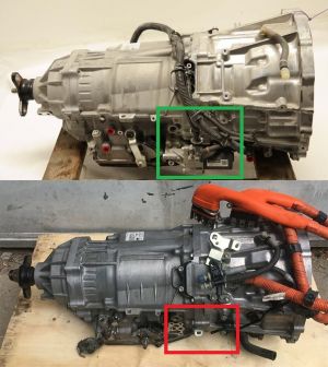
[[File:GS450h oil pump check.jpg|thumb|reference image showing the pump fitted (green), and not fitted red)]] | |||
As built, the GS450h supplies oil pressure to the gearbox using either the ICE engine or an electrically-driven external pump. With the input shaft locked in EV applications, the external pump is the only option available. As mentioned previously, this is a vital part of the setup and it's strongly recommended to buy a transmission that still has it fitted. To help with this, here is a reference photo of what to look for. | |||
<br> | |||
<br>The Internal pump and pressure regulator provides a steady 7 Bar oil pressure.<ref>https://www.youtube.com/watch?v=9RXtNTp1AFw&t=154s&ab_channel=DamienMaguire</ref><br> | |||
<br>The recommended oil is Toyota ATF-WS, though people have had success with 3rd party equivalents.<br> | |||
<br> | |||
<br> | |||
<br> | |||
==== Wiring and control ==== | |||
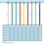
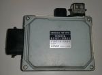
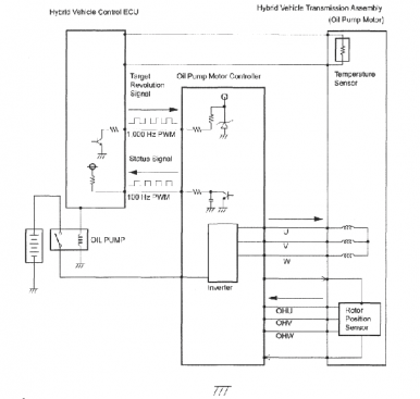
[[File:GS450h oil pump controller.jpg|thumb|GS450h oil pump controller|alt=|150x150px]]The external pump also requires a controller, which uses a [[wikipedia:Pulse-width_modulation|PWM]] control scheme. Although this is rarely included with the transmission, it's quite affordably and widely available (Toyota part number: G1167-30020) | |||
Brown (pin 7) is feedback from the oil pump. It's | ===== Pinouts, schematics and notes ===== | ||
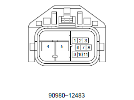
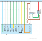
[[File:Connector_-_A55_Oil_Pump_Motor_Controller_90980–12483.png|alt=|right|269x269px]] | |||
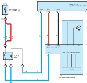
[[File:Oilpump.png|alt=|right|300x300px]] | |||
* The metal case is the ground. | |||
* Black (pin 6) is PWM in from your controller. | |||
* Brown (pin 7) is PWM feedback from the oil pump. It is not required and can be left disconnected. | |||
* The fat blue wire (pin 5) is 12V power. The oil pump uses around 50A Max. So plan for that. Add your own relay to stop it draining your battery while the car is off. | |||
* The PWM for this is weird, it's not just 0-100. IIRC it is 0% at both ends, and rises to 100% near the middle, then back down again. This is just based on the sound of the pump with no load, so needs more testing to find the real values. | |||
[[File:Oil_Pump.png|alt=|386x386px]] | |||
[[File:Gearbox_oil_pump_PWM.jpg|alt=|frameless]] | |||
====Hardware==== | |||
=== | |||
As per ggeter: | As per ggeter: | ||
"For those, like me, who didn't get the pump with the transmission unit, here are the part numbers for bolts and (what appears to be a metal) gasket." | "For those, like me, who didn't get the pump with the transmission unit, here are the part numbers for bolts and (what appears to be a metal) gasket." | ||
Bolts (4) 90080-10197 $2.76 ea | Bolts (4) 90080-10197 $2.76 ea. | ||
Gasket (1) 35142-30010 $14 | Gasket (1) 35142-30010 $14 | ||
The oil pump also contains 3 black rubber | The oil pump also contains 3 black rubber O-rings: | ||
1 x 55mm internal diameter, 2.5mm cross section (for the black outer cover) | 1 x 55mm internal diameter, 2.5mm cross section (for the black outer cover) | ||
| Line 119: | Line 134: | ||
== Wiring Harness Connectors == | == Wiring Harness Connectors == | ||
Here are a list of connectors required for the GS450h transmission & inverter if you need/wish to build the harness for your build. (It is a good idea to find components with at least the connectors to build on. As some of the connectors are impossible to obtain) | Here are a list of connectors required for the GS450h transmission & inverter if you need/wish to build the harness for your build. (It is a good idea to find components with at least the connectors to build on. As some of the connectors are impossible to obtain) | ||
=== Inverter Connectors === | |||
==== OEM ==== | |||
{| class="wikitable" | {| class="wikitable" | ||
!Connector | !Connector | ||
!Part No. | !Toyota Part No. | ||
!Location | !Location | ||
! | !Terminals | ||
!QTY | |||
!Terminal Size Opt 1 | |||
!Terminal Size Opt 2 | |||
!Terminal Size Opt 3 | |||
!Notes | |||
|- | |||
| rowspan="6" |Inverter interface connector (A62) | |||
| rowspan="6" |Toyota | |||
90980–12630 | |||
| rowspan="6" |Black connector on the side of the inverter. | |||
'''This connector is not sold anywhere to our knowledge.''' | |||
| rowspan="3" |0.64 mm .025" | |||
| rowspan="3" |36 - Female | |||
!'''.13 mm<sup>2</sup> / 26 AWG''' | |||
!'''.22-.35 mm<sup>2</sup> / 24-22 AWG''' | |||
!'''.5 mm<sup>2</sup> / 20 AWG''' | |||
| | |||
|- | |||
|Sumitomo 8240-0336 (Tin) | |||
|Sumitomo 8100-3455 (Tin) | |||
|8240-0287 (Tin) | |||
| | |||
|- | |- | ||
| | |Sumitomo 8240-0337 (Gold) | ||
| | |Sumitomo | ||
| | |||
8100-3456 (Gold) | |||
|8240-0288 (Gold) | |||
| | | | ||
|- | |||
| rowspan="3" |2.3 II | |||
0.040" | |||
| rowspan="3" |4 - Female | |||
!'''.3-.5 mm<sup>2</sup> (22-20 AWG)''' | |||
!'''.5-1.25 mm<sup>2</sup> (20-16 AWG)''' | |||
!'''2.0 mm<sup>2</sup> (14 AWG)''' | |||
| rowspan="3" |6mm Pitch Type | |||
(Low Insertion | |||
Force Variant) | |||
|- | |||
|8100-0460 - (Tin) | |||
|8100-0461 (Tin) | |||
|8100-0462 (Tin) | |||
|- | |||
|8100-1344 - (Gold) | |||
|8100-0594 (Gold) | |||
|8100-0817 (Gold) | |||
|} | |} | ||
A good alternative to this | |||
=== OEM Wiring Harness === | |||
The wiring harness goes by the official name of Engine Room Main Wire. Here are the OEM part numbers for the harness over the years: | |||
82111-30K60 - 2007 | |||
82111-30K61 - 2007-2008 | |||
82111-30K62 - 2007-2009 | |||
82111-30K63 - 2008-2010 | |||
82111-30K64 - 2009-2011 | |||
82111-30K65 - 2010-2011 | |||
==== Alternatives ==== | |||
A good alternative to this otherwise difficult to obtain connector is to replace the receptacle/header with the following parts from Molex: | |||
===== Molex MX123 series ===== | |||
{| class="wikitable" | {| class="wikitable" | ||
!Image | !Image | ||
!Part No. | !Part No. | ||
| Line 175: | Line 258: | ||
|} | |} | ||
===== Assembly Instructions ===== | |||
Instructions on how to assemble the MX123 connector can be found here <ref>https://www.molex.com/mx_upload/family/MX123UserManual.pdf (Backup: [https://web.archive.org/web/20220129215727/https://www.molex.com/mx_upload/family/MX123UserManual.pdf Web Archive])</ref>. | |||
===== Pinout ===== | |||
Use the following pinout to remap the internal connections from the Toyota plug to the Molex plug: | |||
[[File:Inverter connections.png|none|thumb|GS450h Inverter/converter internal connections]] | |||
[[File:Gs450h-inverter-wires.jpg|thumb|281x281px|Gs450h-inverter-wires - small white connectors inside the inverter|none]] | |||
=== Transmission Connectors === | |||
[[File:Image.png|none|thumb|GS450 transmission main connection locations]] | |||
{| class="wikitable" | {| class="wikitable" | ||
!Connector | !Connector | ||
!Toyota Part No. | |||
!Part No. | !Part No. | ||
!Terminals | |||
!QTY | |||
!Terminal Size Opt 1 | |||
!Terminal Size Opt 2 | |||
!Terminal Size Opt 3 | |||
!Location | !Location | ||
! | ! | ||
|- | |- | ||
|ECT Solenoid (E83) | | rowspan="3" |ECT Solenoid (E83) | ||
|Sumitomo 6189-1092 | | rowspan="3" |Toyota 90980-12326 | ||
|Located on the left hand side of the transmission above the oil pan. | | rowspan="3" |Sumitomo 6189-1092 | ||
|[[File:Sumitomo 6189-1092.jpg|center|frameless|100x100px]] | | rowspan="3" |'''TS 025 Series''' | ||
( 0.025" | |||
0.64mm ) | |||
| rowspan="3" |Female - 13 | |||
!'''.13 mm<sup>2</sup> / 26 AWG''' | |||
!'''.22-.35 mm<sup>2</sup> / 24-22 AWG''' | |||
!'''.5 mm<sup>2</sup> / 20 AWG''' | |||
| rowspan="3" |Located on the left hand side of the transmission above the oil pan. | |||
| rowspan="3" |[[File:Sumitomo 6189-1092.jpg|center|frameless|100x100px]] | |||
|- | |||
|Sumitomo 8240-0336 (Tin) | |||
|Sumitomo 8100-3455 (Tin) | |||
|8240-0287 (Tin) | |||
|- | |||
|Sumitomo 8240-0337 (Gold) | |||
|Sumitomo | |||
8100-3456 (Gold) | |||
|8240-0288 (Gold) | |||
|- | |||
| rowspan="6" |Shift Lever Position Sensor (E80) | |||
| rowspan="6" |Toyota 90980-12362 | |||
| rowspan="6" |Sumitomo 90980-12362 | |||
| rowspan="3" |'''TS 025 Series''' | |||
( 0.025" | |||
0.64mm ) | |||
| rowspan="3" |Female - 7 | |||
!'''<u>20-22 AWG /</u>''' | |||
'''<u>.3-.5 mm<sup>2</sup></u>''' | |||
!'''<u>16-18 AWG /</u>''' | |||
'''<u>.85-1.25 mm<sup>2</sup></u>''' | |||
!'''<u>14 AWG / 2.0 mm<sup>2</sup></u>''' | |||
| rowspan="6" |Located on the right side of the transmission next to the shift lever inhibitor switch. | |||
| rowspan="6" |[[File:Sumitomo 90980-12362.png|center|frameless|100x100px]] | |||
|- | |||
|Yazaki - 7116-4025 (Tin) | |||
|Yazaki - 7116-4026 (Tin) | |||
|Yazaki - 7116-4027 (Tin) | |||
|- | |- | ||
| | |Yazaki - 7116-4028-08 (Gold) | ||
| | |Yazaki | ||
| | 7116-4029-08 (Gold) | ||
| | |||
|- | |- | ||
|MG1 & MG2 Resolver(s) (E81 & E82) | | rowspan="3" |'''TS 090II Sealed Series''' | ||
|Sumitomo 6189-1240 | |||
|Two connectors located on the left side of the transmission by the bell housing. | ( 0.090" / | ||
|[[File:Sumitomo 6189-1240.jpg|center|frameless|100x100px]] | 2.3mm ) | ||
(6mm LIF variant) | |||
| rowspan="3" |Female - 2 | |||
!'''.3-.5 mm<sup>2</sup> (22-20 AWG)''' | |||
!'''.5-1.25 mm<sup>2</sup> (20-16 AWG)''' | |||
!'''2.0 mm<sup>2</sup> (14 AWG)''' | |||
|- | |||
|8100-0460 - (Tin) | |||
|8100-0461 (Tin) | |||
|8100-0462 (Tin) | |||
|- | |||
|8100-1344 - (Gold) | |||
|8100-0594 (Gold) | |||
|8100-0817 (Gold) | |||
|- | |||
| rowspan="3" |MG1 & MG2 Resolver(s) (E81 & E82) | |||
| rowspan="3" |Toyota 90980-12520 | |||
| rowspan="3" |Sumitomo 6189-1240 | |||
| rowspan="3" |'''TS 025 Series''' | |||
(0.025" | |||
0.64 mm) | |||
| rowspan="3" |Female - 8 | |||
!'''.13 mm<sup>2</sup> / 26 AWG''' | |||
!'''.22-.35 mm<sup>2</sup> / 24-22 AWG''' | |||
!'''.5 mm<sup>2</sup> / 20 AWG''' | |||
| rowspan="3" |Two connectors located on the left side of the transmission by the bell housing. | |||
| rowspan="3" |[[File:Sumitomo 6189-1240.jpg|center|frameless|100x100px]] | |||
|- | |||
|Sumitomo 8240-0336 (Tin) | |||
|Sumitomo 8100-3455 (Tin) | |||
|8240-0287 (Tin) | |||
|- | |||
|Sumitomo 8240-0337 (Gold) | |||
|Sumitomo | |||
8100-3456 (Gold) | |||
|8240-0288 (Gold) | |||
|- | |||
| | |||
| | |||
| | |||
| | |||
| | |||
| | |||
| | |||
| | |||
| | |||
| | |||
|- | |||
|Vehicle Speed Sensor Connector | |||
|Toyota # 90980-11153 [?] | |||
|S-1530 [?] | |||
| | |||
| | |||
| | |||
| | |||
| | |||
| | |||
| | |||
|} | |||
{| class="wikitable" | |||
|+Standardized TS Series Seals and Plugs For Harnesses | |||
!TS 025 Series | |||
! | |||
! | |||
!Seal | |||
! colspan="2" |Plug | |||
|- | |||
!0.64mm | |||
!Wire Insulation Dia. | |||
!Color | |||
!Part Number | |||
!Color | |||
!Part No | |||
|- | |||
|TS 025 SL1 | |||
|0.85-0.95 mm (.033-.037 in) | |||
|Light Brown | |||
|7165-1423 | |||
|Grey | |||
|Toyota 90980-09871 | |||
|- | |||
|TS 025 SL2 | |||
|0.95-1.05 mm (.037-.041 in) | |||
|Green | |||
|7165-1043 | |||
|Grey | |||
|Yazaki 7158-3043-40 | |||
|- | |||
|TS 025 SL3 | |||
|1.1-1.4 mm (.043-.055 in) | |||
|Violet | |||
|7165-1312 | |||
| | |||
| | |||
|- | |||
|TS 025 SL4 | |||
|1.4-1.5 mm (.055-.059 in) | |||
|Dark Yellow | |||
|7165-1198 | |||
| | |||
| | |||
|- | |||
|TS 025 SL5 | |||
|1.6-1.7 mm (.063-.067 in) | |||
|Red Violet | |||
|7165-1199 | |||
| | |||
| | |||
|- | |||
| | |||
| | |||
| | |||
| | |||
| | |||
| | |||
|- | |||
|'''TS 090 II Series''' | |||
|1.4-1.8 mm (.055-.071 in) | |||
|Blue | |||
|7158-3006-90 | |||
| | |||
|Yazaki 7157-8761 | |||
|- | |||
|'''2.3mm''' | |||
|2.0-2.2 mm (.079-.087 in) | |||
|Grey | |||
|7158-3007-10 | |||
| | |||
| | |||
|- | |||
| | |||
|2.3-2.7 mm (.090-.106 in) | |||
|Brown | |||
|7158-3008-80 | |||
| | |||
| | |||
|} | |} | ||
=== Oil Pump & Oil Pump Motor Controller === | |||
{| class="wikitable" | {| class="wikitable" | ||
!Connector | !Connector | ||
!Part No. | !Part No. | ||
!Location | !Location | ||
|- | |- | ||
|Oil Pump Temperature Sensor | |Oil Pump Temperature Sensor | ||
|Sumitomo 6189-0175 | |Sumitomo 6189-0175 | ||
|The connector is the small 2-pin connector in the middle of the harness between the oil pump and controller | |The connector is the small 2-pin connector in the middle of the harness between the oil pump and controller | ||
|- | |- | ||
|HVECU -> Oil Pump Controller (A52) | |HVECU -> Oil Pump Controller (A52) | ||
| | |Toyota 90980-12483 | ||
|Single large (7-way) connector on the side of the oil pump controller | |Single large (7-way) connector on the side of the oil pump controller | ||
|} | |} | ||
==Control | === 3D Printable Parts === | ||
https://grabcad.com/library/gs450-inverter-hv-inlet-blank-1 | |||
[[File:GS450H Inlet Blank .jpg|center|156x156px]] | |||
https://grabcad.com/library/gs450h-side-port-1 | |||
[[File:GS450H-3D-PRINTABLE-HV-INLET.jpg|center|thumb|100x100px]] | |||
https://openinverter.org/forum/viewtopic.php?t=1694 | |||
==Control Schemes== | |||
===ZombieVerter VCU=== | |||
As of 2022, the preferred solution (and the only one under active development) is the [[ZombieVerter VCU]] | |||
==== Zombieverter pinouts and wiring diagram for the GS450H ==== | |||
[[File:Zomb-con-et2.png|none|thumb|GS450H pinouts and wiring diagram for Zombieverter VCU]] | |||
====Lexus GS450h VCU (deprecated)==== | |||
{| class="wikitable mw-collapsible mw-collapsed" role="presentation" | |||
|<strong>Lexus GS450h VCU (deprecated)</strong> | |||
|- | |||
| | |||
'''''UPDATE:''' the dedicated Lexus GS450h VCU has been superseded/replaced by the [[ZombieVerter VCU]]. This section is kept active solely as legacy documentation and differs in important ways from the ZombieVerter implementation.'' | |||
The Lexus GS450h VCU is an open source project to repurpose 2006-2012 Lexus GS450h inverters for DIY EV use. It consists of a circuit board and programming that communicates with the original logic board in the inverter and allows independent control of it without requiring a GS450h ECU. | |||
An open-source VCU, designed by Damien Maguire, can be purchased as a partially populated board on his website: <ref name=":1">https://www.evbmw.com/index.php/evbmw-webshop/vcu-boards/gs450h-vcu (Backup: [https://web.archive.org/web/20221016171604/https://www.evbmw.com/index.php/evbmw-webshop/vcu-boards/gs450h-vcu Web Archive])</ref>[[File:Transmission.png|thumb|147x147px|GS450h transmission and oil pump temperature sensor]] | |||
The VCU is an external unit that will not fit within the GS450h inverter housing. It does not replace the GS450h inverter control board, instead it interfaces with it over USART. | The VCU is an external unit that will not fit within the GS450h inverter housing. It does not replace the GS450h inverter control board, instead it interfaces with it over USART. | ||
A full schematic for the system can be found at [https://openinverter.org/forum/viewtopic.php?p=12105#p12105 this link] | A full schematic for the system can be found at [https://openinverter.org/forum/viewtopic.php?p=12105#p12105 this link] | ||
Note that in addition to the VCU, inverter and transmission, a specific | Note that in addition to the VCU, inverter and transmission, a specific CAN bus connected shunt (ISA shunt) is required: [[Isabellenhütte Heusler]] | ||
For those who have purchased the fully built board, the mating connectors for the VCU are Molex parts: | For those who have purchased the fully built board, the mating connectors for the VCU are Molex parts: | ||
* 33472-2002 (Left side, grey in colour) | *33472-2002 (Left side, grey in colour) | ||
* 33472-2001 (Right side, black in colour) | *33472-2001 (Right side, black in colour) | ||
* 33012-2002 (Crimp terminals) | *33012-2002 (Crimp terminals) | ||
* 5810130065 (Enclosure) | *5810130065 (Enclosure) | ||
For partially populated board, these additional parts are required: | For partially populated board, these additional parts are required: | ||
* 5810140011 (Header, 40 Pos) | *5810140011 (Header, 40 Pos.) | ||
* 75867-101LF (CONN1, Header for | *75867-101LF (CONN1, Header for Wi-Fi module) | ||
* 5787834-1 (CONN2, USB 2.0 receptacle) | *5787834-1 (CONN2, USB 2.0 receptacle) | ||
* TR10S05 (IC10, 5V DC/DC converter) | *TR10S05 (IC10, 5V DC/DC converter) | ||
These parts are available from many electronics distributors. | These parts are available from many electronics distributors. | ||
== VCU Firmware == | ====VCU Firmware==== | ||
Firmware to run on the VCU is available on Github : https://github.com/damienmaguire/Lexus-GS450H-Inverter-Controller | Firmware to run on the VCU is available on Github : https://github.com/damienmaguire/Lexus-GS450H-Inverter-Controller | ||
| Line 256: | Line 557: | ||
This firmware is intended as a stop gap measure before a new Openinverter based version with a web based interface becomes available. (expect mid 2021). | This firmware is intended as a stop gap measure before a new Openinverter based version with a web based interface becomes available. (expect mid 2021). | ||
====Instructions for use==== | |||
Connect a USB cable between the VCU and a PC. | Connect a USB cable between the VCU and a PC. | ||
| Line 412: | Line 712: | ||
Parameters stored to EEPROM | Parameters stored to EEPROM | ||
An option is provided to set the speed in % (0 to 100%) for the electric gearbox | An option is provided to set the speed in % (0 to 100%) for the electric gearbox oil pump. In this example we set the speed to 50% : | ||
Type v50 followed by enter. A response like this will display: | Type v50 followed by enter. A response like this will display: | ||
| Line 418: | Line 718: | ||
Configured gearbox oil pump speed: 50 | Configured gearbox oil pump speed: 50 | ||
I have found in testing on the E65 that 50% is a good value for keeping oil pressure up , providing cooling etc without running the pump too hard. Your millage may vary. | I have found in testing on the E65 that 50% is a good value for keeping oil pressure up , providing cooling etc. without running the pump too hard. Your millage may vary. | ||
An option is provided to shift between LOW and HIGH gear in the GS450H gearbox. Shifts are inhibited at MG1 or MG2 speeds above 100rpm for safety at this time. | An option is provided to shift between LOW and HIGH gear in the GS450H gearbox. Shifts are inhibited at MG1 or MG2 speeds above 100rpm for safety at this time. | ||
| Line 448: | Line 748: | ||
Currently this "simple" firmware does not support contactor control. This may be provided in a later version. | Currently this "simple" firmware does not support contactor control. This may be provided in a later version. | ||
====Wi-Fi Display==== | |||
A Wi-Fi web browser based display is provided in order to easily visualise data from the inverter and gearbox. | |||
Once powered, the Wi-Fi module will create an open access point with an SSID like ESP-XXXX where XXXX will be a series of letters and numbers. | |||
Connect to this access point with any Wi-Fi enabled device (e.g. laptop, tablet, phone etc.). | |||
Connect to this access point with any | |||
Some modern devices will try to access the internet, not find it, and pop up a warning. Dismiss this and open a web browser. | Some modern devices will try to access the internet, not find it, and pop up a warning. Dismiss this and open a web browser. | ||
| Line 464: | Line 763: | ||
Note that the voltage display is derived from the voltage reported by the inverter and both current (amps) and power (kw) gauges are inoperative as of this release. | Note that the voltage display is derived from the voltage reported by the inverter and both current (amps) and power (kw) gauges are inoperative as of this release. | ||
You may wish to change the | You may wish to change the SSID and add a passphrase to the access point. To do this goto : 192.168.4.1/admin | ||
A simple set of dialog boxes will allow the SSID, passphrase and background colour of the gauge display to be set. | |||
In newer versions (October 2020 onwards) of the VCU Board, the default SSID and Password will be `gs450h_vcu` and `inverter123` respectively. | |||
==Development History== | ====Development History==== | ||
V1 - This board was sold tested but also as a bare logic board requiring purchase of your own components and SMD placement and soldering skills. https://www.evbmw.com/index.php/evbmw-webshop/toyota-bare-boards/gs450h-bare-pcb | V1 - This board was sold tested but also as a bare logic board requiring purchase of your own components and SMD placement and soldering skills. https://www.evbmw.com/index.php/evbmw-webshop/toyota-bare-boards/gs450h-bare-pcb (No longer available). | ||
V2 - A new board source was found to be both high quality and low cost. The boards were redesigned around the inventory of parts available from this supplier. In particular the high cost of populated and soldered boards (10x the price) from the source used to make the v1 boards is so significantly lower on the v2 that there are likely no savings by building and soldering the board yourself. Software is still in development. | V2 - A new board source was found to be both high quality and low cost. The boards were redesigned around the inventory of parts available from this supplier. In particular the high cost of populated and soldered boards (10x the price) from the source used to make the v1 boards is so significantly lower on the v2 that there are likely no savings by building and soldering the board yourself. Software is still in development. | ||
==Vendors== | ====Vendors==== | ||
There are currently no vendors who offer support on any aspects of the GS450h VCU. | '''EVBMW:''' <ref name=":1" /> | ||
==Support== | '''NOTE:''' There are currently no vendors who offer support on any aspects of the GS450h VCU. | ||
====Support==== | |||
Community support is available on the [https://openinverter.org/forum/viewtopic.php?f=14&t=396 Lexus GS450H VCU Support Thread] | Community support is available on the [https://openinverter.org/forum/viewtopic.php?f=14&t=396 Lexus GS450H VCU Support Thread] | ||
|} | |||
== See also == | |||
* [[Builds#Lexus GS450h|Builds using a Lexus GS450h transmission as motor]] | |||
== Citations == | |||
[[Category:Toyota]] | |||
[[Category:Inverter]] | |||
<references /> | |||
[[Category:Motor]] | |||
[[Category:Gearbox]] | |||
Latest revision as of 11:15, 13 April 2025
Inverter
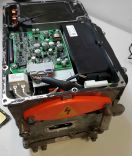
The Lexus GS450h is a hybrid vehicle. Their inverters are suitable and attractive for DIY EVs because of:
- Good availability and price - an inverter and "transmission" can generally be purchased for less than £/€1000.
- Durability. Toyota engineers appear to have made the inverters foolproof, many inputs and outputs gracefully handle fault conditions.
- Respectable performance. Rated for a combined 250kW output.
- Ease of repurposing. Emulating the original ECU seems reasonably feasible. The transmission is a similar size and layout to many RWD transmissions.
The Lexus GS450h (2006-2012 model years) has a variety of useful components inside the inverter package:
- Two high power inverters, for the 2 motors MG1 capable of handling >430 Amps, and MG2 capable of handling >215 Amps. [1][2]
- A boost module to boost the 288v battery pack up to 650v as used in the Lexus (Note that voltages this high are not required for EV conversions).
For technical analysis of this unit, see pages 14-47 of this document: [3]
If you combine a LHD transmission with a RHD inverter (or vice versa) you might end up with a motor that is juddering, not spinning. IN this case you need to swap any two phase cables of both MG1 and MG2.
The inverter is capable of running at full speeds on pack voltages from approx. 280V upwards. The maximum allowable input voltage is 650V, so far, many have found that "standard" EV voltages of 300V-360V to be well suited.
Note that even though the inverter maximum voltage rating is 650V, a 650V battery pack is not required to run this unit. It is capable of excellent performance at lower voltages, such as the typical 300V-360V found in most EVs. However, there is the opportunity to use larger packs with this unit if required in your application.
Should a higher voltage pack be chosen in your application for any reason, the buck/boost converter can be used to power auxiliary equipment at its native voltage.
Weight: 40 lbs
Dimensions: 14" x 9-1/2" x 8-1/2"
Note: If using Zombieverter, the inverter needs powering up after Zombie, use Zombie to power up the inverter.
Buck/Boost Converter
A buck/boost converter lives within the inverter housing, originally this is used to step up the 288V battery pack in the GS450h to the 650V for use in the inverter in the GS. (Note that this does not mean the inverter requires 650V to run, it is simply a maximum rating) For those using a 600+V battery pack, this converter can be used to step the voltage down to a more reasonable level to interface with chargers, DCDC converters, heaters, AC compressors, and other components which can be found in "regular" EV's (Tesla, LEAF, Volt, etc.).
This unit is rated at 30kW, making it unsuitable for traction power, but good for auxiliary devices.
Details on how to control the converter are here: https://openinverter.org/forum/viewtopic.php?f=14&t=538
For technical analysis of this unit, see pages 14-47 of this document: [3]
Do not connect your HV battery to the OEM battery location, for conversion you have to bypass the buck/boost converter and connect directly to the HV bus. See the 3D printable parts below to help with this.
Transmission
For technical analysis of this transmission, see pages 46 and onward of this document:[4]
Motor information and ratios are as follows:
MG1 speed is -2.29:1[5]
MG1 rated speed is not known at this time and recommended to stick to the same speed as MG2
MG2 speed can be 1.9:1 or 3.9:1[5]
MG2 is rated at 300Nm and max 10,230 rpm[4]
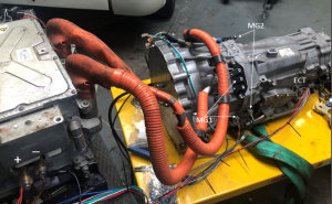
The transmission contains two "Motor-Generator" units. MG1 sits at the front of the transmission, and interfaces with the internal combustion engine through a planetary gear set. For this reason, to obtain torque from MG1, the input shaft of the transmission must be locked in place. This is usually done using a splined coupler, which is then welded onto the transmission front mount.
The input shaft on the transmission has 21 splines, with a 28mm major diameter. There are several Toyota clutches which have this in their centre. The original GS450h flywheel and coupler also contains the appropriate splined centre, of course.
The fluid fill port is the banjo bolt for the upper transmission cooler hose. The specified fluid is "Toyota WS" ATF.
It is a good idea to replace the two bearings in the electric oil pump before fitting a used transmission. There is a guide here[6]. Bearing part numbers are 61900-2Z and 608-2Z, you will need one of each.
The shift position lever on the right-hand side of the transmission engages the parking pawl when in the "all-the-way-back" position. All other positions disengage this pawl. The R, N, D, M positions only affect the output of the shift position sensor.
Note the following when purchasing the transmission:
- It is recommended to purchase one which has the electric oil pump fitted - these are a costly item as the bearings in them often fail, in some cases they cost more than the transmission. More on this in the Oil Pump section below.
- It is recommended to purchase a transmission which includes the wiring harness, or at least off-cuts of the connectors. Some connectors may be unavailable for purchase. There is a thread here which covers the connectors on this transmission.
- It is recommended to purchase the damper assembly with the transmission in order to lock MG1 as noted above. If you can not get the damper assembly, another option is to use the clutch disc from a Toyota 3B (probably also 13BT, 1HZ). These clutch discs have the same 21 spline/diameter configuration. One application is a "1983 Toyota Land Cruiser BJ-60 5spd manual". One Toyota part number is 31250-36230 (there are many depending on vintage) and you will find lots of crosses to 3rd party parts. [2] This was first discovered in this [3] post.
Dimensions
- Overall height (oil pan to top of bellhousing) is 39cm. Bell housing is full height, i.e. 39cm diameter, when the transmission is sitting on its oil pan (as it is on my bench), the bellhousing still just about touches the bench.
- Widest point is 40cm, includes a bump for a starter motor which I don't believe the GS450h even has. Likely leftover to mate with the 2GR engine.
- Overall length including tailshaft, output flange, and pilot shaft, is 82cm.
- Transmission is tapered quite heavily, the width and height is closer to 25cm after the bellhousing, but hard to gauge due to various outcropping parts (motor cables, oil pump, PRNDL selector, etc.)
- Weight is 128kg. Unknown if this is dry or filled. Likely partially filled. Unknown if this includes oil pump and cables.
- The input shaft pokes out 29mm from the general highest point of the back of the bell housing? (e.g. set a 20cm ruler there and measure from it)
- The taper at the tip of the shaft before the splines appear fully is 6mm long. (i.e. the length of the tip portion without proper splines)
- The output flange bolt pattern is 52.5mm radius (about 91mm from hole to hole). It does not seem to have a machined flange surface, only the 22.5mm diameter ~3.2mm deep recesses around the bolt holes are machined. Pilot shaft diameter is 16mm. Internally the flange has 26 quite rectangular splines. (not 27 or so like Toyota's more common off-road applications).
Oil Pump
Overview and location
As built, the GS450h supplies oil pressure to the gearbox using either the ICE engine or an electrically-driven external pump. With the input shaft locked in EV applications, the external pump is the only option available. As mentioned previously, this is a vital part of the setup and it's strongly recommended to buy a transmission that still has it fitted. To help with this, here is a reference photo of what to look for.
The Internal pump and pressure regulator provides a steady 7 Bar oil pressure.[7]
The recommended oil is Toyota ATF-WS, though people have had success with 3rd party equivalents.
Wiring and control
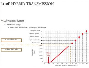
The external pump also requires a controller, which uses a PWM control scheme. Although this is rarely included with the transmission, it's quite affordably and widely available (Toyota part number: G1167-30020)
Pinouts, schematics and notes
- The metal case is the ground.
- Black (pin 6) is PWM in from your controller.
- Brown (pin 7) is PWM feedback from the oil pump. It is not required and can be left disconnected.
- The fat blue wire (pin 5) is 12V power. The oil pump uses around 50A Max. So plan for that. Add your own relay to stop it draining your battery while the car is off.
- The PWM for this is weird, it's not just 0-100. IIRC it is 0% at both ends, and rises to 100% near the middle, then back down again. This is just based on the sound of the pump with no load, so needs more testing to find the real values.
Hardware
As per ggeter: "For those, like me, who didn't get the pump with the transmission unit, here are the part numbers for bolts and (what appears to be a metal) gasket."
Bolts (4) 90080-10197 $2.76 ea.
Gasket (1) 35142-30010 $14
The oil pump also contains 3 black rubber O-rings:
1 x 55mm internal diameter, 2.5mm cross section (for the black outer cover)
2 x 50mm internal diameter, 2.5mm cross section (between each 'layer' of the pump housing).
The oil pump motor cover is held onto the pump housing by 4 M5 x 16mm flanged screws.
Wiring Harness Connectors
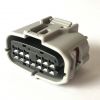
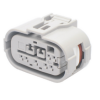
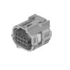
Here are a list of connectors required for the GS450h transmission & inverter if you need/wish to build the harness for your build. (It is a good idea to find components with at least the connectors to build on. As some of the connectors are impossible to obtain)
Inverter Connectors
OEM
| Connector | Toyota Part No. | Location | Terminals | QTY | Terminal Size Opt 1 | Terminal Size Opt 2 | Terminal Size Opt 3 | Notes |
|---|---|---|---|---|---|---|---|---|
| Inverter interface connector (A62) | Toyota
90980–12630 |
Black connector on the side of the inverter.
This connector is not sold anywhere to our knowledge.
|
0.64 mm .025" | 36 - Female | .13 mm2 / 26 AWG | .22-.35 mm2 / 24-22 AWG | .5 mm2 / 20 AWG | |
| Sumitomo 8240-0336 (Tin) | Sumitomo 8100-3455 (Tin) | 8240-0287 (Tin) | ||||||
| Sumitomo 8240-0337 (Gold) | Sumitomo
8100-3456 (Gold) |
8240-0288 (Gold) | ||||||
| 2.3 II
0.040" |
4 - Female | .3-.5 mm2 (22-20 AWG) | .5-1.25 mm2 (20-16 AWG) | 2.0 mm2 (14 AWG) | 6mm Pitch Type
(Low Insertion Force Variant) | |||
| 8100-0460 - (Tin) | 8100-0461 (Tin) | 8100-0462 (Tin) | ||||||
| 8100-1344 - (Gold) | 8100-0594 (Gold) | 8100-0817 (Gold) |
OEM Wiring Harness
The wiring harness goes by the official name of Engine Room Main Wire. Here are the OEM part numbers for the harness over the years:
82111-30K60 - 2007
82111-30K61 - 2007-2008
82111-30K62 - 2007-2009
82111-30K63 - 2008-2010
82111-30K64 - 2009-2011
82111-30K65 - 2010-2011
Alternatives
A good alternative to this otherwise difficult to obtain connector is to replace the receptacle/header with the following parts from Molex:
Molex MX123 series
| Image | Part No. | Item | Quantity |
|---|---|---|---|
| 036638-0002 | CMC header connector 48pin | 1 | |
| 064320-1311 | CMC receptacle 48pin | 1 | |
| 064320-1301 | CMC wire cap | 1 | |
| 064323-1039 | CP terminal | 4 | |
| 064322-1039 | CP terminal | 32 | |
| 064325-1010 | CMC plug | 8 | |
| 064325-1023 | CMC plug | 4 |
Assembly Instructions
Instructions on how to assemble the MX123 connector can be found here [8].
Pinout
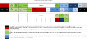
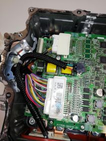
Use the following pinout to remap the internal connections from the Toyota plug to the Molex plug:
Transmission Connectors
| Connector | Toyota Part No. | Part No. | Terminals | QTY | Terminal Size Opt 1 | Terminal Size Opt 2 | Terminal Size Opt 3 | Location | |
|---|---|---|---|---|---|---|---|---|---|
| ECT Solenoid (E83) | Toyota 90980-12326 | Sumitomo 6189-1092 | TS 025 Series
( 0.025" 0.64mm )
|
Female - 13 | .13 mm2 / 26 AWG | .22-.35 mm2 / 24-22 AWG | .5 mm2 / 20 AWG | Located on the left hand side of the transmission above the oil pan. | |
| Sumitomo 8240-0336 (Tin) | Sumitomo 8100-3455 (Tin) | 8240-0287 (Tin) | |||||||
| Sumitomo 8240-0337 (Gold) | Sumitomo
8100-3456 (Gold) |
8240-0288 (Gold) | |||||||
| Shift Lever Position Sensor (E80) | Toyota 90980-12362 | Sumitomo 90980-12362 | TS 025 Series
( 0.025" 0.64mm )
|
Female - 7 | 20-22 AWG /
.3-.5 mm2 |
16-18 AWG /
.85-1.25 mm2 |
14 AWG / 2.0 mm2 | Located on the right side of the transmission next to the shift lever inhibitor switch. | |
| Yazaki - 7116-4025 (Tin) | Yazaki - 7116-4026 (Tin) | Yazaki - 7116-4027 (Tin) | |||||||
| Yazaki - 7116-4028-08 (Gold) | Yazaki
7116-4029-08 (Gold) |
||||||||
| TS 090II Sealed Series
( 0.090" / 2.3mm ) (6mm LIF variant) |
Female - 2 | .3-.5 mm2 (22-20 AWG) | .5-1.25 mm2 (20-16 AWG) | 2.0 mm2 (14 AWG) | |||||
| 8100-0460 - (Tin) | 8100-0461 (Tin) | 8100-0462 (Tin) | |||||||
| 8100-1344 - (Gold) | 8100-0594 (Gold) | 8100-0817 (Gold) | |||||||
| MG1 & MG2 Resolver(s) (E81 & E82) | Toyota 90980-12520 | Sumitomo 6189-1240 | TS 025 Series
(0.025" 0.64 mm) |
Female - 8 | .13 mm2 / 26 AWG | .22-.35 mm2 / 24-22 AWG | .5 mm2 / 20 AWG | Two connectors located on the left side of the transmission by the bell housing. | |
| Sumitomo 8240-0336 (Tin) | Sumitomo 8100-3455 (Tin) | 8240-0287 (Tin) | |||||||
| Sumitomo 8240-0337 (Gold) | Sumitomo
8100-3456 (Gold) |
8240-0288 (Gold) | |||||||
| Vehicle Speed Sensor Connector | Toyota # 90980-11153 [?] | S-1530 [?] |
| TS 025 Series | Seal | Plug | |||
|---|---|---|---|---|---|
| 0.64mm | Wire Insulation Dia. | Color | Part Number | Color | Part No |
| TS 025 SL1 | 0.85-0.95 mm (.033-.037 in) | Light Brown | 7165-1423 | Grey | Toyota 90980-09871 |
| TS 025 SL2 | 0.95-1.05 mm (.037-.041 in) | Green | 7165-1043 | Grey | Yazaki 7158-3043-40 |
| TS 025 SL3 | 1.1-1.4 mm (.043-.055 in) | Violet | 7165-1312 | ||
| TS 025 SL4 | 1.4-1.5 mm (.055-.059 in) | Dark Yellow | 7165-1198 | ||
| TS 025 SL5 | 1.6-1.7 mm (.063-.067 in) | Red Violet | 7165-1199 | ||
| TS 090 II Series | 1.4-1.8 mm (.055-.071 in) | Blue | 7158-3006-90 | Yazaki 7157-8761 | |
| 2.3mm | 2.0-2.2 mm (.079-.087 in) | Grey | 7158-3007-10 | ||
| 2.3-2.7 mm (.090-.106 in) | Brown | 7158-3008-80 | |||
Oil Pump & Oil Pump Motor Controller
| Connector | Part No. | Location |
|---|---|---|
| Oil Pump Temperature Sensor | Sumitomo 6189-0175 | The connector is the small 2-pin connector in the middle of the harness between the oil pump and controller |
| HVECU -> Oil Pump Controller (A52) | Toyota 90980-12483 | Single large (7-way) connector on the side of the oil pump controller |
3D Printable Parts
https://grabcad.com/library/gs450-inverter-hv-inlet-blank-1
https://grabcad.com/library/gs450h-side-port-1
https://openinverter.org/forum/viewtopic.php?t=1694
Control Schemes
ZombieVerter VCU
As of 2022, the preferred solution (and the only one under active development) is the ZombieVerter VCU
Zombieverter pinouts and wiring diagram for the GS450H
Lexus GS450h VCU (deprecated)
| Lexus GS450h VCU (deprecated) |
|
UPDATE: the dedicated Lexus GS450h VCU has been superseded/replaced by the ZombieVerter VCU. This section is kept active solely as legacy documentation and differs in important ways from the ZombieVerter implementation.
The VCU is an external unit that will not fit within the GS450h inverter housing. It does not replace the GS450h inverter control board, instead it interfaces with it over USART.
A full schematic for the system can be found at this link Note that in addition to the VCU, inverter and transmission, a specific CAN bus connected shunt (ISA shunt) is required: Isabellenhütte Heusler
For partially populated board, these additional parts are required:
These parts are available from many electronics distributors. VCU FirmwareFirmware to run on the VCU is available on Github : https://github.com/damienmaguire/Lexus-GS450H-Inverter-Controller This guide relates to V3.01 available here on Github : https://github.com/damienmaguire/Lexus-GS450H-Inverter-Controller/blob/master/Software/gs450h_v3_user.ino A video tutorial to accompany this guide and firmware is available here :https://vimeo.com/501777258 In order to aid those not familiar with programming, a new firmware with a basic serial interface is now available. This will be the default loaded onto all VCU boards sold on the EVBMW webshop as of 18/01/21. This firmware is intended as a stop gap measure before a new Openinverter based version with a web based interface becomes available. (expect mid 2021). Instructions for useConnect a USB cable between the VCU and a PC. Using a serial terminal program of your choice, connect at 115200,8,N,1. Once connected, type ? and press enter. The following menu should then display : =========== EVBMW GS450H VCU Version 3.01 ============== ************ List of Available Commands ************ ? - Print this menu d - Print received data from inverter D - Print configuration data f - Calibrate minimum throttle. g - Calibrate maximum throttle. i - Set max drive torque (0-3500) e.g. typing i200 followed by enter sets max drive torque to 200 q - Set max reverse torque (0-3500) e.g. typing q200 followed by enter sets max reverse torque to 200 v - Set gearbox oil pump speed (0-100%) e.g. typing v50 followed by enter sets oil pump to 50% speed a - Select LOW gear. s - Select HIGH gear. z - Save configuration data to EEPROM memory ************************************************************** The menu system allows for the display of data from both the VCU, GS450H Inverter and gearbox as well as setting of parameters such as throttle calibration and maximum torque. To select a menu option type its associated character followed by enter. ? Will display the menu. d Displays data from the inverter in this format : 0 1 2 3 4 5 6 7 8 9 ------------------------------------------------------------------------------ 00 | 0 0 10 | 0 0 0 0 0 0 0 0 20 | 0 0 0 0 0 0 0 0 0 0 30 | 0 0 0 0 0 0 40 | 0 0 0 0 0 0 0 0 50 | 0 0 0 0 0 60 | 70 | 80 | 0 0 0 0 0 0 90 | 0 0 0 0 0 0 0 0 MTH Valid: Yes Checksum: 0 DC Bus: ----v MG1 - Speed: 0rpm Position: 0 MG2 - Speed: 0rpm Position: 0 Water Temp: 0.00c Inductor Temp: 0.00c Another Temp: 0c Another Temp: 0c D (capital or large D) displays VCU configuration data as well as information on the Gearbox status in this format : *************************************************************************************************** Throttle Channel 1: 109 Throttle Channel 2: 53 Commanded Torque: 0 Selected Direction: DRIVE Selected Gear: HIGH Configured Max Drive Torque: 600 Configured Max Reverse Torque: 300 Configured gearbox oil pump speed: 40 Current valve positions: PB1:ON PB2:ON PB3:ON MG1 Stator temp: 109.69 MG2 Stator temp: 109.69 *************************************************************************************************** Throttle calibration procedure : Set your throttle, be it a pedal or potentiometer or other, to the position of desired zero throttle. Type f and press enter. A response like this will display: Configured min throttle value: 109 Now press or advance the throttle to the desired position of maximum throttle. Type g and press enter. A response like this will display: Configured max throttle value: 633 The throttle calibration is now complete. Next we want to set the maximum allowed drive and reverse torque values. The GS450H inverter will accept a value of between 0 and 3500 for torque. for initial bench and vehicle testing it is advisable to limit these to low values. In this example we will set drive torque to 500 and reverse torque to 300. First, drive torque: Type i500 followed by enter. A response like this will display: Configured drive torque: 500 Now reverse torque: Type q250 followed by enter. A response like this will display: Configured reverse torque: 250 Torque calibration is now complete. At this point it is advised to store the now configured values to EEPROM (non volatile memory) by typing z followed by enter. A response like this will display: Parameters stored to EEPROM An option is provided to set the speed in % (0 to 100%) for the electric gearbox oil pump. In this example we set the speed to 50% : Type v50 followed by enter. A response like this will display: Configured gearbox oil pump speed: 50 I have found in testing on the E65 that 50% is a good value for keeping oil pressure up , providing cooling etc. without running the pump too hard. Your millage may vary. An option is provided to shift between LOW and HIGH gear in the GS450H gearbox. Shifts are inhibited at MG1 or MG2 speeds above 100rpm for safety at this time. To select LOW gear type a and press enter. A response like this will display: LOW Gear Selected To select HIGH gear type s and press enter. A response like this will display: HIGH Gear Selected It is advised to leave HIGH gear selected always at this time until further testing and development has been completed. Finally, store all parameters to EEPROM once more by typing z and press enter. A response like this will display: Parameters stored to EEPROM Selecting Direction. The firmware supports the use of the IN1 and IN2 pins of the V2 VCU as direction control inputs. Operation is as follows : If both inputs are unconnected, NEUTRAL is selected. In neutral , no torque commands are transmitted to the inverter regardless of throttle application. If IN1is connected to +12v , DRIVE is selected. In drive both MG1 and MG2 provide torque in a forward direction to the gearbox output shaft. If IN2 is connected to +12v , REVERSE is selected. In reverse only MG2 provides torque in a reverse direction to the gearbox output shaft. Currently this "simple" firmware does not support contactor control. This may be provided in a later version. Wi-Fi DisplayA Wi-Fi web browser based display is provided in order to easily visualise data from the inverter and gearbox. Once powered, the Wi-Fi module will create an open access point with an SSID like ESP-XXXX where XXXX will be a series of letters and numbers. Connect to this access point with any Wi-Fi enabled device (e.g. laptop, tablet, phone etc.). Some modern devices will try to access the internet, not find it, and pop up a warning. Dismiss this and open a web browser. Type 192.168.4.1 into the address bar and press enter. Again, some modern devices and browsers will complain that it is not a secure connection etc. Just dismiss the warning and proceed. After a few seconds the web gauge display will appear. Note that the voltage display is derived from the voltage reported by the inverter and both current (amps) and power (kw) gauges are inoperative as of this release. You may wish to change the SSID and add a passphrase to the access point. To do this goto : 192.168.4.1/admin A simple set of dialog boxes will allow the SSID, passphrase and background colour of the gauge display to be set. In newer versions (October 2020 onwards) of the VCU Board, the default SSID and Password will be `gs450h_vcu` and `inverter123` respectively. Development HistoryV1 - This board was sold tested but also as a bare logic board requiring purchase of your own components and SMD placement and soldering skills. https://www.evbmw.com/index.php/evbmw-webshop/toyota-bare-boards/gs450h-bare-pcb (No longer available). V2 - A new board source was found to be both high quality and low cost. The boards were redesigned around the inventory of parts available from this supplier. In particular the high cost of populated and soldered boards (10x the price) from the source used to make the v1 boards is so significantly lower on the v2 that there are likely no savings by building and soldering the board yourself. Software is still in development. VendorsEVBMW: [9] NOTE: There are currently no vendors who offer support on any aspects of the GS450h VCU. SupportCommunity support is available on the Lexus GS450H VCU Support Thread |
See also
Citations
- ↑ https://toyota-club.net/files/faq/21-12-01_faq_hybrid_tr_en.htm
- ↑ https://www.osti.gov/biblio/947393see p. 62 for locked rotor test. 430A needed for 300Nm of MG2 torque, which is the official published value for the LS600h. (interestingly gs450h published value is 275Nm, although the two should share the same MG units and inverter). MG1 could possibly handle just as much, since copper amount is similar. But the inverter has half as many IGBTs for MG1 as MG2, so the current at system level is possibly halved.
- ↑ 3.0 3.1 https://www.osti.gov/servlets/purl/928684
- ↑ 4.0 4.1 https://www.osti.gov/servlets/purl/947393
- ↑ 5.0 5.1 [1]
- ↑ http://carlthomas66.blogspot.com/2016/03/lexus-gs450h-transmission-oil-pump.html (Backup: Web Archive)
- ↑ https://www.youtube.com/watch?v=9RXtNTp1AFw&t=154s&ab_channel=DamienMaguire
- ↑ https://www.molex.com/mx_upload/family/MX123UserManual.pdf (Backup: Web Archive)
- ↑ 9.0 9.1 https://www.evbmw.com/index.php/evbmw-webshop/vcu-boards/gs450h-vcu (Backup: Web Archive)
