Volkswagen Heater: Difference between revisions
Jump to navigation
Jump to search
No edit summary |
|||
| (20 intermediate revisions by 6 users not shown) | |||
| Line 1: | Line 1: | ||
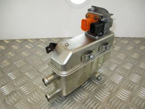
VW heater | [[File:VW heater.jpg|thumb]] | ||
== General Information <ref>http://datasheets.dbk-worldwide.com/EN/Datasheets/WireHeaters/DBKITM_HV%20Water%20heater_eng.pdf (Backup: [http://web.archive.org/web/20221016161226/http://datasheets.dbk-worldwide.com/EN/Datasheets/WireHeaters/DBKITM_HV%20Water%20heater_eng.pdf Web Archive])</ref> == | |||
[ | * Operating Voltage: 280VDC - 450VDC | ||
* Power: 5kW (7kW "boost" between 350-450V) | |||
* Control via LIN by integrated electronics | |||
* Temperature control by integrated sensor | |||
* 3d Scan: [https://grabcad.com/library/vw-egolf-gte-electric-water-heater-1 https://grabcad.com/] | |||
* Must be used in an inverted orientation with the sockets situated below as air can be left trapped in the heater element zone causing steam to be explosively generated | |||
== Dimensions == | |||
* | * Fluid connection (mm): 20 (Nozzle dimensions according to DIN3021-3<ref>https://web.archive.org/web/20250109134824/https://images.carid.com/mubea/items/pdf/hose-spring-band-clamp-brochure.pdf</ref>) | ||
* | * Dimensions L x W x H (mm): 210 x 73 x175 | ||
* Weight (kg): ~1,7 <br /> | |||
== Pinout/Connectors == | |||
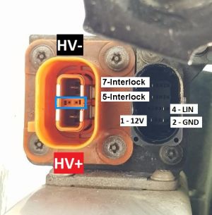
[[File:VW heater connectors (annotated) V2.jpg|thumb]] | |||
HV connector: TE 4-2103177-5 (HVA 280 series - key "E") | |||
* HV+ near to the body, | |||
*HV- far from the body | |||
LV connector: TE 1-1394416-1 | |||
* | * Pin 1 is permanent 12V | ||
* Pin 2 is GND | |||
*Pin 4 is LIN | |||
*Pin 5 is HV Interlock loop passthrough (ref. right terminal highlighted with Blue in picture) | |||
*Pin 7 is HV interlock loop passthrough (ref. left terminal highlighted with Blue in picture) | |||
==LIN Bus Communication == | |||
{| class="wikitable" | |||
|+Control and Answer Messages from/to Heater<ref>https://openinverter.org/forum/viewtopic.php?p=26604#p26604</ref> | |||
!ID | |||
!Description | |||
!Length | |||
!Checksum Type | |||
!Byte 0 | |||
!Byte 1 | |||
!Byte 2 | |||
! Byte 3 | |||
!Byte 4 | |||
!Byte 5 | |||
!Byte 6 | |||
!Byte 7 | |||
|- | |||
|Dec: 28 | |||
Hex: 0x1C | |||
PID: 0x9C | |||
|Control, every 50ms | |||
|2 | |||
|Enhanced | |||
|Power | |||
0-100% | |||
scale: x1 | |||
| Last bit: Start/Stop | |||
| | |||
| | |||
| | |||
| | |||
| | |||
| | |||
|- | |||
|Dec: 48 | |||
Hex: 0x30 | |||
* | PID: 0xF0 | ||
* | |Feedback | ||
* | |8 | ||
|Enhanced | |||
|HV Current: | |||
Unit: Amp | |||
Scale: 0.25 | |||
|?? | |||
|?? | |||
|?? | |||
|LV Voltage: | |||
Unit: Volt | |||
Scale: 0.1 | |||
|Module Temp | |||
Unit: Celcius | |||
offset:-50 | |||
|Temperature in | |||
Unit: Celsius | |||
offset:-50 | |||
|Temperature out | |||
Unit: Celsius | |||
offset:-50 | |||
|} | |||
==VW Part Numbers== | |||
Heater: | |||
*3Q0 963 231 A | |||
*3Q0 963 231 C | |||
*3Q0 963 231 E | |||
Cable assemblies: | |||
* HV cable is 3Q0 971 475 or 5Q0 971 475 | |||
* LV cable appears to be 1J0 973 714 | |||
==References== | |||
<references /> | |||
[[Category:VAG]] | |||
[[Category:Heater Coolant]] | |||
Latest revision as of 08:54, 23 April 2025

General Information [1]
- Operating Voltage: 280VDC - 450VDC
- Power: 5kW (7kW "boost" between 350-450V)
- Control via LIN by integrated electronics
- Temperature control by integrated sensor
- 3d Scan: https://grabcad.com/
- Must be used in an inverted orientation with the sockets situated below as air can be left trapped in the heater element zone causing steam to be explosively generated
Dimensions
- Fluid connection (mm): 20 (Nozzle dimensions according to DIN3021-3[2])
- Dimensions L x W x H (mm): 210 x 73 x175
- Weight (kg): ~1,7
Pinout/Connectors

HV connector: TE 4-2103177-5 (HVA 280 series - key "E")
- HV+ near to the body,
- HV- far from the body
LV connector: TE 1-1394416-1
- Pin 1 is permanent 12V
- Pin 2 is GND
- Pin 4 is LIN
- Pin 5 is HV Interlock loop passthrough (ref. right terminal highlighted with Blue in picture)
- Pin 7 is HV interlock loop passthrough (ref. left terminal highlighted with Blue in picture)
LIN Bus Communication
| ID | Description | Length | Checksum Type | Byte 0 | Byte 1 | Byte 2 | Byte 3 | Byte 4 | Byte 5 | Byte 6 | Byte 7 |
|---|---|---|---|---|---|---|---|---|---|---|---|
| Dec: 28
Hex: 0x1C PID: 0x9C |
Control, every 50ms | 2 | Enhanced | Power
0-100% scale: x1 |
Last bit: Start/Stop | ||||||
| Dec: 48
Hex: 0x30 PID: 0xF0 |
Feedback | 8 | Enhanced | HV Current:
Unit: Amp Scale: 0.25 |
?? | ?? | ?? | LV Voltage:
Unit: Volt Scale: 0.1 |
Module Temp
Unit: Celcius offset:-50 |
Temperature in
Unit: Celsius offset:-50 |
Temperature out
Unit: Celsius offset:-50 |
VW Part Numbers
Heater:
- 3Q0 963 231 A
- 3Q0 963 231 C
- 3Q0 963 231 E
Cable assemblies:
- HV cable is 3Q0 971 475 or 5Q0 971 475
- LV cable appears to be 1J0 973 714
References
- ↑ http://datasheets.dbk-worldwide.com/EN/Datasheets/WireHeaters/DBKITM_HV%20Water%20heater_eng.pdf (Backup: Web Archive)
- ↑ https://web.archive.org/web/20250109134824/https://images.carid.com/mubea/items/pdf/hose-spring-band-clamp-brochure.pdf
- ↑ https://openinverter.org/forum/viewtopic.php?p=26604#p26604