Chevrolet Volt Coolant Pumps: Difference between revisions
Jump to navigation
Jump to search
No edit summary |
Categories |
||
| (8 intermediate revisions by 2 users not shown) | |||
| Line 1: | Line 1: | ||
I reviewed Ampera manual and came to a page describing | I reviewed Ampera manual and came to a page describing Coolant Pump Connector and PWM activation pin.<br> | ||
[[File:Coolant pump wiring.png|thumb|Coolant Pump Wiring]] | I applied 1kHz signal from makeshift 5V generator at 50% – 75% duty and pump responded and spooled up at low to medium speed.<br> | ||
Link to my experiments: https://leafdriveblog.wordpress.com/2018/12/28/pumps-and-fans/<br> | |||
Wires in connector need to be connected according to this picture. <br> | |||
Pin1 – enable 12V<br> | |||
Pin2 – signal feedback<br> | |||
Pin3 – PWM control<br> | |||
Pin4 – GND<br> | |||
Pin5 - 12V supply<br> | |||
[[File:Coolant pump.png|thumb|Coolant pump]] | |||
{| class="wikitable" | |||
|+ | |||
|[[File:Coolant pump wiring.png|thumb|Coolant Pump Wiring]] | |||
|} | |||
[[Category:Water pumps]] | |||
[[Category:Chevrolet]] | |||
Latest revision as of 16:37, 20 December 2024
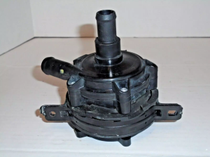
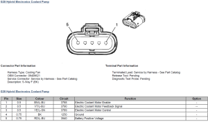
I reviewed Ampera manual and came to a page describing Coolant Pump Connector and PWM activation pin.
I applied 1kHz signal from makeshift 5V generator at 50% – 75% duty and pump responded and spooled up at low to medium speed.
Link to my experiments: https://leafdriveblog.wordpress.com/2018/12/28/pumps-and-fans/
Wires in connector need to be connected according to this picture.
Pin1 – enable 12V
Pin2 – signal feedback
Pin3 – PWM control
Pin4 – GND
Pin5 - 12V supply

 |