Honda Accelerator pedal sensor: Difference between revisions
Jump to navigation
Jump to search
→General Information: Added dimensioned photos. |
Beggernator (talk | contribs) Added revised pinout for UK model sensors. |
||
| (One intermediate revision by one other user not shown) | |||
| Line 8: | Line 8: | ||
The voltage from both sensors ramps linearly from the fully released position to the fully depressed position<ref>Add reference</ref>. The pedal should be supplied with a reasonable stable and accurate 5V supply to ensure a proper readout. | The voltage from both sensors ramps linearly from the fully released position to the fully depressed position<ref>Add reference</ref>. The pedal should be supplied with a reasonable stable and accurate 5V supply to ensure a proper readout. | ||
{| class="wikitable" | {| class="wikitable" | ||
|+Voltage Output of Throttle Sensors | |+Voltage Output of Throttle Sensors | ||
| Line 24: | Line 25: | ||
|} | |} | ||
==Versions== | |||
UK spec versions have different pinout. | |||
When connected correctly sensor 1 is half the scale of sensor 2, fully pressed yielded max values of 1432 for Pot1 and 2980 for Pot2 on a v3 mini mainboard. | |||
{| class="wikitable" | |||
|+Pinout of UK Spec Accord / CRV APP | |||
(P/N TBC) | |||
!Connector Pin | |||
!A | |||
!B | |||
!C | |||
!D | |||
!E | |||
!F | |||
|- | |||
|Function | |||
|5V REF 1 | |||
|GND 1 | |||
|SIG 1 | |||
|SIG 2 | |||
|5V REF 2 | |||
|GND 2 | |||
|} | |||
(In OEM application pins E and F are swapped, giving SIG 2 an inverted output, this isn't compatible with open inverter so a pin swap is needed) | |||
== Versions == | |||
{| class="wikitable" | {| class="wikitable" | ||
|+Selected Versions | |+Selected Versions | ||
| Line 64: | Line 91: | ||
[[File:With cover and bracket.jpg|none|thumb|With cover and bracket, P/N 37971-RCA-A01 (Honda Element)]] | [[File:With cover and bracket.jpg|none|thumb|With cover and bracket, P/N 37971-RCA-A01 (Honda Element)]] | ||
[https://grabcad.com/library/honda-accelerator-pedal-sensor-scan-1 3D scan of bracket, sensor, and cover] | |||
= References = | |||
<references /> | <references /> | ||
[[Category:Honda]] | [[Category:Honda]] | ||
[[Category:Accelerator pedals and position sensors]] | [[Category:Accelerator pedals and position sensors]] | ||
Latest revision as of 09:28, 16 August 2025
General Information
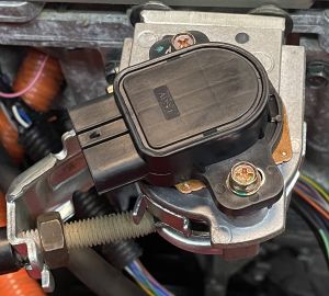
The original cable is shielded to avoid interference from other sources and resulting unwanted acceleration or deceleration.
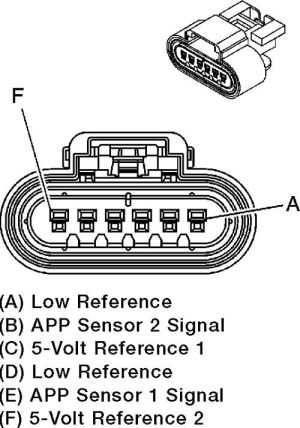
The voltage from both sensors ramps linearly from the fully released position to the fully depressed position[2]. The pedal should be supplied with a reasonable stable and accurate 5V supply to ensure a proper readout.
| Pedal Position | Sensor 1 | Sensor 2 |
|---|---|---|
| Fully Released | 0.05 V | 4.30 V |
| Fully Depressed | 0.10 V | 4.90 V |
UK spec versions have different pinout.
When connected correctly sensor 1 is half the scale of sensor 2, fully pressed yielded max values of 1432 for Pot1 and 2980 for Pot2 on a v3 mini mainboard.
| Connector Pin | A | B | C | D | E | F |
|---|---|---|---|---|---|---|
| Function | 5V REF 1 | GND 1 | SIG 1 | SIG 2 | 5V REF 2 | GND 2 |
(In OEM application pins E and F are swapped, giving SIG 2 an inverted output, this isn't compatible with open inverter so a pin swap is needed)
Versions
| Part Number | Cars Used In | Electrical Connector | Remarks |
|---|---|---|---|
|
|
|
Connector can be found on Aliexpress |
Photos
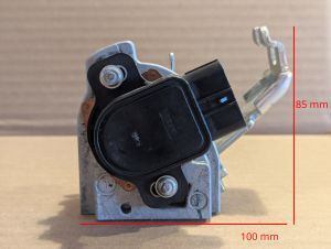
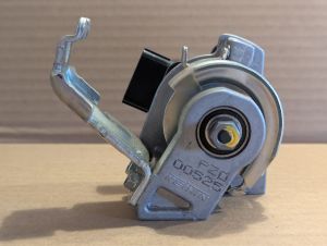
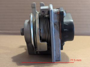
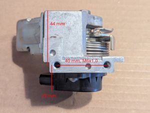

3D scan of bracket, sensor, and cover
References
- ↑ Forum Reference: https://openinverter.org/forum/viewtopic.php?p=66006#p66006
- ↑ Add reference