Tesla Model S Front HVJB: Difference between revisions
Jason arnold (talk | contribs) added "Dimensions" heading, added LV connector part number and pinout pic |
Jason arnold (talk | contribs) →LV: added paragraph detailing LV pinout |
||
| Line 26: | Line 26: | ||
* Blue: DC-DC Converter - fused internally at "F4" (20A) | * Blue: DC-DC Converter - fused internally at "F4" (20A) | ||
* Orange: A/C Compressor - fused internally at "F2" (40A) | * Orange: A/C Compressor - fused internally at "F2" (40A) | ||
* Brown: PTC Cabin Heater | * Brown: PTC Cabin Heater - fused internally at "F3" (40A) | ||
=== LV === | === LV === | ||
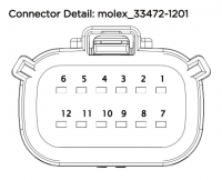
The LV connector on the bottom left side is a 12-pin Molex MX150 series (Molex p/n: [https://www.molex.com/molex/products/part-detail/crimp_housings/0334721201 33472-1201]). Only 6 of the 12 pins are populated, as follows: | The LV connector on the bottom left side is a 12-pin Molex MX150 series (Molex p/n: [https://www.molex.com/molex/products/part-detail/crimp_housings/0334721201 33472-1201]). Only 6 of the 12 pins are populated, as follows: | ||
{| class="wikitable" | {| class="wikitable" | ||
|+[[File:Connector-Tesla-FJB.png|200x200px]]<small>( | |+LV pinout[[File:Connector-Tesla-FJB.png|200x200px]]<small>(harness view)</small> | ||
!pin | !pin | ||
!function | !function | ||
| Line 42: | Line 42: | ||
|- | |- | ||
|6 | |6 | ||
| | |STATUS out | ||
|- | |- | ||
|10 | |10 | ||
| Line 48: | Line 48: | ||
|- | |- | ||
|11 | |11 | ||
|HVIL in | |HVIL in (not needed) | ||
|- | |- | ||
|12 | |12 | ||
|HVIL out | |HVIL out (not needed) | ||
|} | |} | ||
The purpose of this LV connector is to control the built-in PWM circuit for the battery heater that is attached via the grey HV plug. The PWM control parameters are known and will be detailed in a future OI Wiki contribution. As noted, HVIL pins 11 & 12 seem to have no effect on the function of the HVJB and can be left de-pinned. | |||
Revision as of 00:19, 28 February 2022

Overview
The second-generation front HVJB (Tesla p/n: 1028843-01-A & 1028843-01-C) found in the early (2012-2016) Model S, isn't particularly useful on its own, but it does enable a number of other HV accessories as literally plug and play.
Unless otherwise noted, info below was sourced from: https://www.diyelectriccar.com/threads/hacking-the-tesla-model-s-front-junction-box.193729/
Dimensions
Case measurements:
- L : 9 1/4in case (10 3/4 to allow for LV connector and ground connection)
- W: 8 1/4in case (9 1/4 to allow for HV plugs to A/C, DC-DC,etc. and HV in)
- H: 2 3/4in case (3 1/4 if the mounting bracket still fitted)
HV hole size:
- less than 15mm, hard to get actual without disassembly, probably 13-14mm diameter
Connections
HV
There are 4 colour-coded HV plugs found along the top side of the unit (as oriented with the front label right side up) that correspond to particular HV systems. From left to right, they are:
- Grey: Battery Fluid Heater - fused internally at "F1" (20A)
- Blue: DC-DC Converter - fused internally at "F4" (20A)
- Orange: A/C Compressor - fused internally at "F2" (40A)
- Brown: PTC Cabin Heater - fused internally at "F3" (40A)
LV
The LV connector on the bottom left side is a 12-pin Molex MX150 series (Molex p/n: 33472-1201). Only 6 of the 12 pins are populated, as follows:
| pin | function |
|---|---|
| 4 | 12V |
| 5 | PWM in |
| 6 | STATUS out |
| 10 | GND |
| 11 | HVIL in (not needed) |
| 12 | HVIL out (not needed) |
The purpose of this LV connector is to control the built-in PWM circuit for the battery heater that is attached via the grey HV plug. The PWM control parameters are known and will be detailed in a future OI Wiki contribution. As noted, HVIL pins 11 & 12 seem to have no effect on the function of the HVJB and can be left de-pinned.
