Getting CAN working on a Teensy 3.6: Difference between revisions
| Line 27: | Line 27: | ||
You can hook up your Teensy to the usual Arduino peripherals to make your device. | You can hook up your Teensy to the usual Arduino peripherals to make your device. | ||
The picture shows a simple CAN-based ammeter | The picture shows a simple CAN-based ammeter made from an [[Isabellenhütte Heusler|Isabellenhütte IVT-S]] and an Adafruit SSD1306 OLED display. The IVT-S CAN bus is connected to the (terminated) CAN0 transceiver and the OLED display is an I2C device connected to SCL (pin 19) and SDA (pin 18). You can find the source code [https://github.com/clanger9/electricdart/blob/master/TeensyMeter.ino here]. | ||
Revision as of 21:54, 10 November 2020

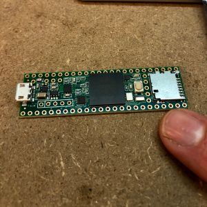
A Teensy 3.6 is an ideal board for making a CAN-compatible device. It's generally compatible with Arduino sketches and hardware, which makes it relatively simple to go from an Arduino-based prototype to the finished article.
Get Teensyduino
The Teensy IDE is a modified version of the Arduino software. You can download it here. Even though it's a separate program, it will make use of your previously-installed Arduino libraries and sketches. Which is pretty neat.
Connect your CAN transceivers

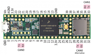
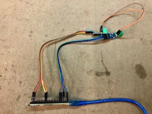
Good news: you can use the same SN65HVD230-based CAN transceivers that you use with a Due. Connect the TX/RX lines to pins 3 & 4 (CAN0) and pins 33 & 34 (CAN1) as well as GND and 3.3V (see pinout diagram).
Test your CAN link
Connect the CAN bus on the two transceivers together (CANL to CANL, CANH to CANH)

Connect your computer to the USB port on the Teensy board.
Download the FlexCAN library and install it in Teensyduino with Sketch -> Include Library -> Add .ZIP Library...
Now you can test your CAN communications with:
File -> Examples -> FlexCAN -> CANTest
Sketch -> Upload
Tools -> Serial Monitor
If your CAN transceivers are working properly, you should be rewarded with incrementing numbers in the serial monitor window.
Build your CAN device

You can hook up your Teensy to the usual Arduino peripherals to make your device.
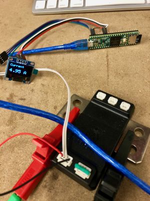
The picture shows a simple CAN-based ammeter made from an Isabellenhütte IVT-S and an Adafruit SSD1306 OLED display. The IVT-S CAN bus is connected to the (terminated) CAN0 transceiver and the OLED display is an I2C device connected to SCL (pin 19) and SDA (pin 18). You can find the source code here.