Tesla Model S/X DC/DC Converter: Difference between revisions
More detailed pinout instructions |
changed DCDC command interval to 100ms |
||
| Line 13: | Line 13: | ||
== Control == | == Control == | ||
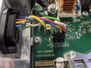
Although CAN control is an option, it is not necessary as the unit will run quite comfortably in failsafe mode (i.e. without any CAN input). Supply 12V to HW-EN (pin 1 on Molex plug), ground the case to the chassis and the converter starts spitting out 13.5V. It has been mentioned that under heavy load the voltage will sag, so to enable CAN control see [https://openinverter.org/forum/viewtopic.php?f=10&t=536 this OI forum thread.] [[File:PXL 20210514 092652934-min.jpg|alt=Pinout for LV connector is written on the board|thumb|Pinout for LV connector is written on the board]]CAN commands to request 14V at 5ms | Although CAN control is an option, it is not necessary as the unit will run quite comfortably in failsafe mode (i.e. without any CAN input). Supply 12V to HW-EN (pin 1 on Molex plug), ground the case to the chassis and the converter starts spitting out 13.5V. It has been mentioned that under heavy load the voltage will sag, so to enable CAN control see [https://openinverter.org/forum/viewtopic.php?f=10&t=536 this OI forum thread.] [[File:PXL 20210514 092652934-min.jpg|alt=Pinout for LV connector is written on the board|thumb|Pinout for LV connector is written on the board]]CAN commands to request 14V at <s>5ms</s> 100ms interval would be 0x2DD, but i need to provide additional +4 value to byte 1 because of enable bit value. Therefore 0x6DD. | ||
Msg is 3 byte long and value of data is swapped little endian so DD is byte0 and 06 is byte1 | Msg is 3 byte long and value of data is swapped little endian so DD is byte0 and 06 is byte1 | ||
Revision as of 19:22, 20 November 2022

Wiring
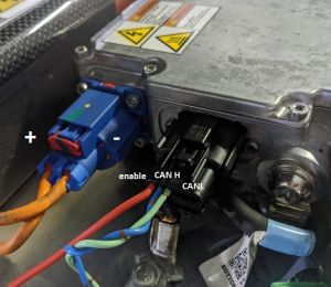
HV connector: KET MG655776 type D
LV connector: Molex 0334721301
HV+ (positive) line is the one on the leftmost - oposite side of the red 12v output bolt.
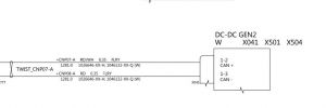
For LV connector pin1 (top row) s the enable pin. Pin2 and pin3 are CAN H and CAN L.


Control
Although CAN control is an option, it is not necessary as the unit will run quite comfortably in failsafe mode (i.e. without any CAN input). Supply 12V to HW-EN (pin 1 on Molex plug), ground the case to the chassis and the converter starts spitting out 13.5V. It has been mentioned that under heavy load the voltage will sag, so to enable CAN control see this OI forum thread.

CAN commands to request 14V at 5ms 100ms interval would be 0x2DD, but i need to provide additional +4 value to byte 1 because of enable bit value. Therefore 0x6DD.
Msg is 3 byte long and value of data is swapped little endian so DD is byte0 and 06 is byte1
CAN ID 0x3D8 MSG DD 06 00
Reporting does not work if enable line is not high. Whenever i turn on enable i see reports.
Report is in telegram 0x210
0x210 8 bytes at 100ms
byte 2 = coolant inlet temp,
byte 3 = input power (16 W/bit),
byte 4 = output current (1 A/bit),
byte 5 = output voltage (0.1 V/bit)