Hyundai Ioniq CCS Charge Inlet 91684-G7010: Difference between revisions
No edit summary |
text edits |
||
| Line 10: | Line 10: | ||
On the right hand side is a resistor block containing a 2.7K resistor between PE and PP. | On the right hand side is a resistor block containing a 2.7K resistor between PE and PP. | ||
[[File:14 way connector top side.jpg|thumb|Wire side of 14 way connector, top side. Pin 1 top right: brown-black, pin 8 below it: black.]] | [[File:14 way connector top side.jpg|thumb|Wire side of 14 way connector, top side. Pin 1 top right: brown-black, pin 8 below it: black.]] | ||
[[File:14 way connector bottom view.jpg|thumb|Bottom view of 14 way connector. Bottom row starts at pin 8, black, at the top]] | |||
There is a 'commoning block' that connects the AC cable shielding, the paired CP/PP cable shielding and PE itself to a common wire into the 14 way connector. | There is a 'commoning block' that connects the AC cable shielding, the paired CP/PP cable shielding and PE itself to a common wire into the 14 way connector. | ||
The inlet has only one thermistor, positioned between the two DC HV cables in the inlet. | |||
There is a 3 way AC connector for the on board charger. | |||
The 14 way connector pinout is described below. Pin numbering starts at the top right pin when looking from the wire side of the plug, and is black/brown. Pin 8 starts on right hand side of bottom row, black. | |||
Pinout: | |||
{| class="wikitable" | |||
|+ | |||
!Pin | |||
!Colour | |||
!Description | |||
|- | |||
|1 | |||
|black/brown | |||
|Shielding of CP/PP pair, also connected to pin 11 and PE earth (pin 12), and shielding of AC cable | |||
|- | |||
|2 | |||
|yellow | |||
|Actuator lock feedback, presumed | |||
|- | |||
|3 | |||
|red | |||
|Actuator lock feedback, presumed | |||
|- | |||
|4 | |||
|blue | |||
|Actuator lock motor | |||
|- | |||
|5 | |||
|orange | |||
|Actuator lock motor | |||
|- | |||
|6 | |||
|white | |||
|Thermistor, presumed NTC 10K, DC cable pair | |||
|- | |||
|7 | |||
|brown | |||
|Thermistor, presumed NTC 10K, DC cable pair | |||
|- | |||
|8 | |||
|black | |||
|Charge port LED -ve | |||
|- | |||
|9 | |||
|red/black | |||
|Charge port LED +ve | |||
|- | |||
|10 | |||
|not used | |||
|not used | |||
|- | |||
|11 | |||
|black/brown | |||
|Shielding of CP/PP pair, also connected to pin 1 and PE earth (pin 12), and shielding of AC cable | |||
|- | |||
|12 | |||
|black | |||
|PE, also connected to pins 1 and 11 | |||
|- | |||
|13 | |||
|2 white wires | |||
|PP. One white wire direct to PP pin at inlet, one white wire to one side of detachable 2.7K resistor. Other side | |||
of resistor (thin blue) goes to commoning block and eventually pin 12, PE. | |||
|- | |||
|14 | |||
|green | |||
|CP | |||
|} | |||
Note that there are no resistors in the inlet CP to 14 way plug, but there is a 2.7K detachable resistor between PP and PE. | |||
Revision as of 07:11, 6 June 2024
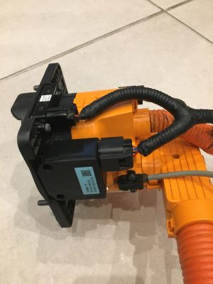
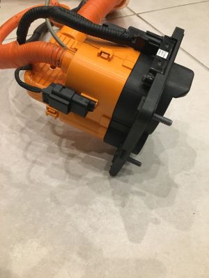
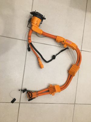
The Hyundai Ioniq AE CCS Charge Inlet part number 91864-G7010 combines a Type 2 charge port (single phase) with a CCS2 DC inlet. The full part is shown below with approx. 2M of shielded DC cable, a TE AMP+ connector for the Hyundai battery pack, connector to onboard charger and 14-way plug presumably connecting to the car's charge controller. There are plastic 'pass through' mouldings that mount and route the HV DC cables, and a cable release for manually releasing the charge port lock pin.

The charge port inlet has a two part backshell, with DC HV cables exiting via a right angle backshell. These are fairly easily removed but the plastic tabs are weak. The charge port lock actuator screws to the left side of the charge port and a manual wire pull release attaches to it to pull the locking pin back out.
An LED is mounted in the top of the port, above the AC input.
On the right hand side is a resistor block containing a 2.7K resistor between PE and PP.
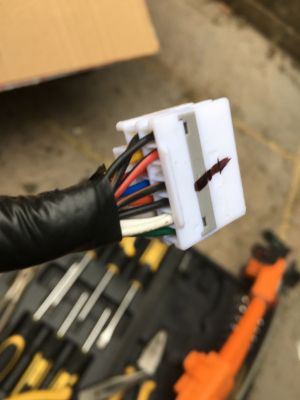
There is a 'commoning block' that connects the AC cable shielding, the paired CP/PP cable shielding and PE itself to a common wire into the 14 way connector.
The inlet has only one thermistor, positioned between the two DC HV cables in the inlet.
There is a 3 way AC connector for the on board charger.
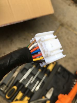
The 14 way connector pinout is described below. Pin numbering starts at the top right pin when looking from the wire side of the plug, and is black/brown. Pin 8 starts on right hand side of bottom row, black.
Pinout:
| Pin | Colour | Description |
|---|---|---|
| 1 | black/brown | Shielding of CP/PP pair, also connected to pin 11 and PE earth (pin 12), and shielding of AC cable |
| 2 | yellow | Actuator lock feedback, presumed |
| 3 | red | Actuator lock feedback, presumed |
| 4 | blue | Actuator lock motor |
| 5 | orange | Actuator lock motor |
| 6 | white | Thermistor, presumed NTC 10K, DC cable pair |
| 7 | brown | Thermistor, presumed NTC 10K, DC cable pair |
| 8 | black | Charge port LED -ve |
| 9 | red/black | Charge port LED +ve |
| 10 | not used | not used |
| 11 | black/brown | Shielding of CP/PP pair, also connected to pin 1 and PE earth (pin 12), and shielding of AC cable |
| 12 | black | PE, also connected to pins 1 and 11 |
| 13 | 2 white wires | PP. One white wire direct to PP pin at inlet, one white wire to one side of detachable 2.7K resistor. Other side
of resistor (thin blue) goes to commoning block and eventually pin 12, PE. |
| 14 | green | CP |
Note that there are no resistors in the inlet CP to 14 way plug, but there is a 2.7K detachable resistor between PP and PE.