Foccci: Difference between revisions
Added 4.5b pin mapping |
added version 4.5b pinout |
||
| Line 3: | Line 3: | ||
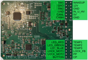
[[File:Foccci 4.5b pinout.png|thumb|Foccci 4.5b pinout]] | |||
This page is about FOCCCI. FOCCCI is an open source CCS Charge Controller started by Uhi and developed by the OpenInverter Community. | This page is about FOCCCI. FOCCCI is an open source CCS Charge Controller started by Uhi and developed by the OpenInverter Community. | ||
Revision as of 13:02, 12 June 2024
Disclaimer: This Page is still work in progress! Any information written here is a draft only and should be handled as such. Contributions more then welcome. If you have questions please ask them in the discussion section of the page or in the OpenInvert Forum.


This page is about FOCCCI. FOCCCI is an open source CCS Charge Controller started by Uhi and developed by the OpenInverter Community.
Here you will find documentation on the Hardware, where to get it (or how to build it yourself), News regarding the development and many more great things.
On Foccci runs the reference software CCS32Clara (also referred to as Clara).
Foccci in the OpenInverter Forum.
Pin description
External connector ("Deutsch Header")
Starting version 4.5b the pins were reshuffled to allow one wiring loom going to the charge port and one to the car side. Changed pins are bold.
| Short name | Pin up to 4.5a | Pin from 4.5b | Description |
|---|---|---|---|
| TEMP1 | A1 | A1 | Power pin temperature sensor. It is pulled up to 3.3V with 10k and the sensor must pull down to GND. Sensor characteristics are configurable in software |
| TEMP2 | A2 | A2 | As above |
| TEMP3 | A3 | A3 | As Above |
| LOCKFB | A4 | A4 | Feedback signal from connector lock. Pulled up to 3.3V with 10k, so feedback must pull down to GND. Thresholds configurable in software |
| IN_U_HV | A5 | B10 | Analog input 0 to 5V, with pull-down-resistor. Can be used to measure the charge port voltage, using a converter board, e.g. the "muehlpower board" |
| CP | A6 | A6 | CP (Control Pilot) pin from charge port |
| SW2(_LS) | A7 | B4 | Output for charge port contactor 2. Low side switch until Foccci 4.4, high side switch starting 4.5
Controls one of the contactors to make the connection between the HV battery and the vehicle inlet. The output can drive inductive load without additional circuits. It will clamp the turn-off voltage to ~40V. The driver has protection against shortcut and thermal overload. The output can be configured to be just digital on/off, and can also be configured to use PWM. BUT: In Foccci versions 4.2 and 4.3 (maybe more) the output driver is only capable of slow PWM, which is hearable and may cause trouble with the contactors. So it is recommended to NOT use the PWM feature, and instead use contactors which do not require economizing or use external economizers. In case you want the PWM nevertheless, you need a external freewheeling diode. Starting Foccci 4.5 PWM is working as intended at 18 kHz. It is a high side output starting v4.5, so the other side of the contactor must be connected to GND. Before v4.5 it is a low side output so the other side must be connected to 12V |
| LOCK_MOT2 | A8 | A8 | Motor driver output for charge port lock servo |
| LOCK_MOT1 | A9 | A9 | |
| PP | A10 | A5 | PP (Proximity Pilot) pin from charge port. If you want Foccci to wake up when an unpowered charge cord is plugged in you must close JP3 to pin 1 (towards R7). There mustn't be a pull-down resistor in the charge port in this case as that would permanently keep Foccci awake |
| 5V | A11 | B11 | 5V, 500mA e.g. for supplying voltage sense board. This is an OUTPUT of Foccci. Do not apply an external voltage source here. Foccci contains a step-down-converter from the 12V supply to this 5V output. |
| GND | A12 | B12 | |
| CANH | B1 | B1 | CAN communication |
| CANL | B2 | B2 | |
| n.c. | B3 | Unused pins were assigned GND in 4.5b | |
| n.c. | B4 | ||
| GND | B5 | B5, B3 | |
| SW1(_LS) | B6 | B6 | Output for the charge port contactor 1. See description of SW2(_LS). |
| WAKEUP | B7 | B7 | Wakeup bus. Momentarily (or constantly) applying 12V wakes up the board. In the other direction Foccci can wake up (or supply with up to 1A) other devices via a 12V high side switch |
| 12V | B8 | B8 | Supply voltage, always on. 9 to 24V are fine. |
| LED_RED | B9 | A12 | Status LEDs |
| LED_GREEN | B10 | A11 | |
| LED_BLUE | B11 | A10 | |
| BUTTON | B12 | A7 | Wakes up Foccci or stops an ongoing charging session |
Internal connectors
| short name | description |
|---|---|
| UART TX | Provides logging information, 921600 Baud. See also https://github.com/uhi22/ccs32clara/blob/main/doc/clara_user_manual.md#serial-logging |
| UART RX | Not used |
| SWCLK | for flashing with STLINK |
| SWDIO | for flashing with STLINK |
Hardware detection

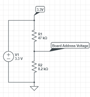
To allow software to reliably detect which version hardware it runs on, in HW version 4.1 a version indication resistor was added. As opposed to some other boards that run at 5.3V, the voltage here is 3.3V.
| Variant | R1 | R2 | voltage | ADC | -3% | +3% |
|---|---|---|---|---|---|---|
| - | 47 | 2,7 | 0,179 | 222 | 216 | 229 |
| - | 47 | 3,3 | 0,217 | 269 | 261 | 277 |
| - | 47 | 3,9 | 0,253 | 314 | 304 | 323 |
| - | 47 | 4,7 | 0,300 | 372 | 361 | 383 |
| - | 47 | 5,1 | 0,323 | 401 | 389 | 413 |
| - | 47 | 5,6 | 0,351 | 436 | 423 | 449 |
| - | 47 | 6,8 | 0,417 | 518 | 502 | 533 |
| - | 47 | 7,5 | 0,454 | 564 | 547 | 580 |
| 4.0 with economizer | 47 | 8,2 | 0,490 | 608 | 590 | 627 |
| - | 47 | 9,1 | 0,535 | 664 | 644 | 684 |
| 4.2 | 47 | 10 | 0,579 | 718 | 697 | 740 |
| 4.3 | 47 | 12 | 0,671 | 833 | 808 | 858 |
| 4.4 | 47 | 15 | 0,798 | 991 | 961 | 1020 |
| 4.5 | 47 | 18 | 0,914 | 1134 | 1100 | 1168 |
| 47 | 22 | 1,052 | 1306 | 1266 | 1345 | |
| 47 | 27 | 1,204 | 1494 | 1449 | 1539 | |
| 47 | 33 | 1,361 | 1689 | 1639 | 1740 | |
| 47 | 39 | 1,497 | 1857 | 1801 | 1913 | |
| 47 | 47 | 1,650 | 2048 | 1986 | 2109 | |
| 47 | 56 | 1,794 | 2226 | 2160 | 2293 |