DNR Reverse Forward Switch Parking Gear Shift: Difference between revisions
No edit summary |
|||
| Line 3: | Line 3: | ||
There is a schematic/connection table is in last pic of my previous post :)<br> | There is a schematic/connection table is in last pic of my previous post :)<br> | ||
Drive outputs pin 2 & 7 | Drive outputs pin 2 & 7<br> | ||
Reverse outputs pin 3 & 6 | Reverse outputs pin 3 & 6<br> | ||
pins 3 & 7 output +12v | pins 3 & 7 output +12v<br> | ||
Pins 2 & 6 output whatever you feed to pin 1. | Pins 2 & 6 output whatever you feed to pin 1.<br> | ||
LEDs are not controllable separately, they switch color depending on selector position.<br> | LEDs are not controllable separately, they switch color depending on selector position.<br> | ||
Revision as of 15:31, 13 September 2024
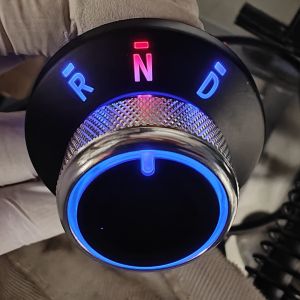
DNR Reverse Forward Switch Parking Gear Shift
A complete directional switch with indication available on Aliexpress.
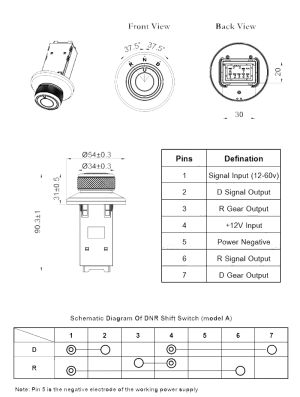
There is a schematic/connection table is in last pic of my previous post :)
Drive outputs pin 2 & 7
Reverse outputs pin 3 & 6
pins 3 & 7 output +12v
Pins 2 & 6 output whatever you feed to pin 1.
LEDs are not controllable separately, they switch color depending on selector position.
This looks to me like it is a mechanical rocker switch with rocker covered with a knob, so nothing fancy in that sense :)
There are two possible outputs for both D & R.
One is positive (connected to the +12v supply, which also powers the leds) and the other output is dependent on the pin 1 connection.
If pin 1 is not connected, you don't get an output from the pins defined as signal outputs.
https://www.aliexpress.com/w/wholesale-DNR-Switch-Forward-Reverse-Parking-Gear-Shift-.html?spm=a2g0o.detail.search.0

