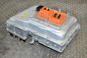
BMW i3 Inverter
BMW I3 inverter

Forum thread: https://openinverter.org/forum/viewtopic.php?p=23214#p23214
BMW i3™ inverter drop-in board Available
https://openinverter.org/shop/index.php?route=product/product&product_id=72
| Pin No | Assigniment | Description |
|---|---|---|
| 1 | 12V | |
| 2 | BRAKE_IN | |
| 3 | PRECHARGE_OUT | |
| 4 | CANL | |
| 5 | CANH | |
| 6 | DCSW_OUT | |
| 7 | FORWARD_IN | |
| 8 | REVERSE_IN | |
| 9 | 5V (OUT) | |
| 10 | RESOLVER_S2/ENCODER_A | Sin Low (blue) |
| 11 | GND | |
| 12 | RESOLVER_S1 | Sin Hi (red) |
| 13 | THROTTLE1 | |
| 14 | THROTTLE2 | |
| 15 | RESOLVER_R1 | Excitation Hi (yellow) |
| 16 | RESOLVER_S3/ENCODER_B | Cos Hi (white) |
| 17 | MTEMP+ | (blue) |
| 18 | MTEMP- | (grey) |
| 19 | RESOLVER_S4 | Cos Low (brown) |
| 20 | EMCYSTOP_IN | |
| 21 | GND | |
| 22 | RESOLVER_R2 | Excitation Low (green) |
| 23 | START_IN |
Note: colours in description column above are for motor sensor wires and currently unconfirmed. See section below on resolver wiring.
There are 2 variants of the i3. one with the REX and one with out.
the REX variant has a additional 25kw inverter to run the onboard generator.
Power stage: Infineon FS800R07 IGBTs rated for 800amps 650v
| Pin No | I/O | Description | Notes | Pin No | I/O | Description | Notes | |
|---|---|---|---|---|---|---|---|---|
| 1 | 21 | GND Switching Mosfets ? | ||||||
| 2 | I | 32V in | 22 | GND Switching Mosfets ? | ||||
| 3 | I | 32V in | 23 | |||||
| 4 | I | IGBT A HI | 24 | |||||
| 5 | I | IGBT A LOW | 25 | |||||
| 6 | I | CS (ADC) | 26 | GND IGBT Driver ground | ||||
| 7 | I | SDI | 27 | GND IGBT Driver ground | ||||
| 8 | I | SDO | 28 | GND IGBT Driver ground | ||||
| 9 | I | SCK | 29 | GND IGBT Driver ground | ||||
| 10 | I | IGBT B HI | 30 | GND IGBT Driver ground | ||||
| 11 | I | IGBT B LOW | 31 | GND IGBT Driver ground | ||||
| 12 | I | IGBT C HI | 32 | GND IGBT Driver ground | ||||
| 13 | I | IGBT C LOW | 33 | 5V IGBT Driver Power | ||||
| 14 | 34 | 5V IGBT Driver Power | ||||||
| 15 | 35 | I | IGBT PSU 12V on | |||||
| 16 | O | IGBT DRIVER UVW Upper Ready | 36 | O | IGBT Driver Fault | |||
| 17 | O | IGBT DRIVER UVW Lower Ready | 37 | I | 5V LEM Current sensor Power | |||
| 18 | O | Current Sense C Signal | 38 | GND Current sensor Ground | ||||
| 19 | O | Current Sense B Signal | 39 | GND Current sensor Ground | ||||
| 20 | O | Current Sense A Signal | 40 | GND Current sensor Ground |
Motor Resolver & Temperature Sensors
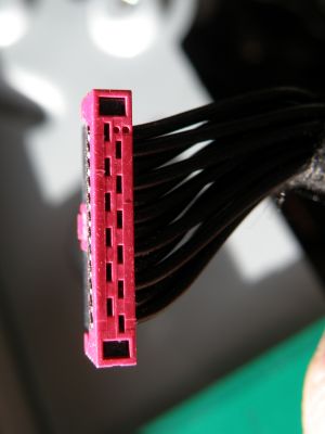
12-pin PCB header to connect to the motor sensors is an ERNI MiniBridge, part number 294920
Wire colours to pin allocation below confirmed by multimeter trace. Resolver coils confirmed by resistance, however sin vs cos and hi vs lo are not confirmed yet, provisional info below in italics, based on forum posts.

| Pin No | Colour | Description | Notes |
|---|---|---|---|
| 1 | Brown | Sin Hi | Twisted pair. 22.4 - 33.6 Ω. |
| 2 | Blue | Sin Lo | |
| 3 | Yellow | Ex Hi | Twisted pair. 22.4 - 33.6 Ω |
| 4 | Green | Ex Lo | |
| 5 | Red | Cos Hi | Twisted pair. 13.6 - 20.4 Ω |
| 6 | White | Cos Lo | |
| 7 | Blue | Temperature
Sensor |
From BMW Service Technical Training Manual - I01 High-voltage Components:
There are two stator coil temperature sensors. The rotor temperature is determined using readings from the stator temperature sensors. |
| 8 | Grey | ||
| 9 | Red | Temperature
Sensor | |
| 10 | Grey | ||
| 11 | - | Unused | These wires terminate in one of the six pin connectors in
the motor housing. There is nothing connected to them. |
| 12 | - | Unused |