Uncategorized files
Jump to navigation
Jump to search
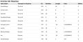
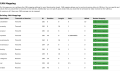
Showing below up to 50 results in range #201 to #250.
-
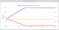
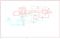 Boost Mode Connection.png 1,176 × 756; 14 KB
-
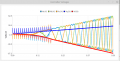
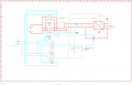 Boost mode variant.png 1,293 × 831; 16 KB
-
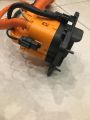
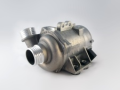
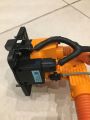
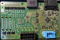
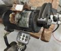 Bosch PWG-3.jpg 2,048 × 1,723; 471 KB
-
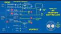
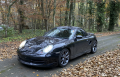 Boxster EV.png 780 × 502; 1.05 MB
-
 Broken isospi.gif 774 × 1,376; 394 KB
-
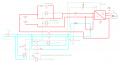 Buck Mode Connection.png 1,463 × 762; 22 KB
-
 CAB300-C SP2.png 1,147 × 662; 108 KB
-
 CAB300-C SP2 CAN instructions.png 1,345 × 734; 188 KB
-
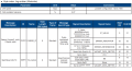
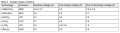
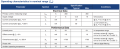 CAB300-C SP2 characteristics.png 1,346 × 551; 154 KB
-
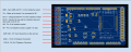
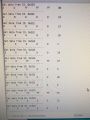 CAN bus messages on serial console.jpg 800 × 1,067; 278 KB
-
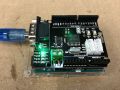 CAN bus shield fitted to Arduino Uno.jpg 800 × 600; 172 KB
-
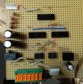 CAN repeater.jpg 1,655 × 1,676; 423 KB
-
CCS1 vs CCS2 signaling circuit.png 21,220 × 4,902; 1.01 MB
-
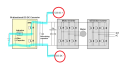
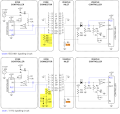 CCS1 vs CCS2 signaling circuit 2.png 995 × 946; 320 KB
-
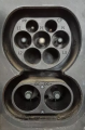
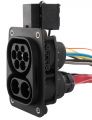 CCS2-inlet.jpg 403 × 527; 134 KB
-
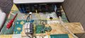 CCS bidirectional charger.jpg 4,000 × 1,800; 1.41 MB
-
 CCS bidirectional charger 2.jpg 1,800 × 4,000; 929 KB
-
 CCS inlet.jpg 4,032 × 3,024; 1.47 MB
-
 CCS inlet rhs.jpg 3,024 × 4,032; 1.6 MB
-
 CCS setup LIM-01.png 2,346 × 1,093; 207 KB
-
 CCS setup LIM 2-02.png 817 × 309; 34 KB
-
 CCS setup LIM 2-03.png 2,584 × 803; 59 KB
-
 CCur.png 816 × 414; 27 KB
-
 CHAdeMO-LeafVCU (1).png 1,600 × 900; 986 KB
-
 CVolt.png 815 × 413; 98 KB
-
 CWA200.png 225 × 169; 48 KB
-
 Can mapping boostech.png 1,116 × 567; 67 KB
-
 Can mapping chademo.png 1,390 × 910; 141 KB
-
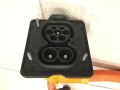
 Ccs-socket.jpg 800 × 800; 67 KB
-
 Ccs mg.png 758 × 1,156; 864 KB
-
 ChaDeMo socket in Touran.jpg 3,264 × 2,448; 2.01 MB
-
 ChademoJumpers.jpg 1,700 × 1,609; 1.29 MB
-
 Chademo Wiring.png 1,492 × 592; 299 KB
-
 Charge inlet backshell.jpg 3,024 × 4,032; 1.47 MB
-
 Chemvolt.png 738 × 202; 35 KB
-
 Clanger boost idea.png 720 × 405; 93 KB
-
 ClipsOnPins-LDUEncoder.jpg 600 × 677; 217 KB
-
 Commands.png 1,232 × 610; 56 KB
-
 Conboxuntouched.webp 1,920 × 1,440; 161 KB
-
 Connector-Tesla-AC-compressor.png 342 × 256; 22 KB
-
 Connector-Tesla-FJB.png 766 × 621; 112 KB
-
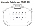
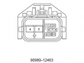 Connector - A55 Oil Pump Motor Controller 90980–12483.png 269 × 201; 7 KB
-
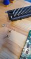 Connector PCB screws.jpg 1,986 × 3,745; 4.84 MB
-
 Connector Secured.jpg 1,651 × 2,148; 2.69 MB
-
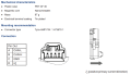
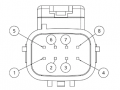
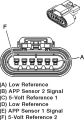 Connector pinout.jpg 500 × 714; 56 KB
-
 Contactor Control.jpg 3,579 × 2,426; 2.21 MB
-
 Contactor gate capacitors.jpg 925 × 591; 118 KB
-
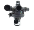 Coolant Control Valve Q65.png 408 × 356; 95 KB
-
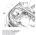 Coolant Heater Control 4way Valve position.png 1,096 × 1,073; 525 KB
-
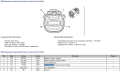 Coolant Heater Control Valve.png 1,779 × 1,052; 216 KB


.png)


