Uncategorized files
Jump to navigation
Jump to search
Showing below up to 50 results in range #601 to #650.
-
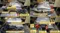
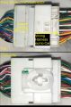
 Prius Gen 2 Inverter.jpg 1,024 × 893; 135 KB
-
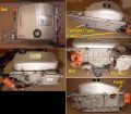
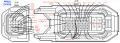
 Prius Gen 2 Layout.jpg 800 × 594; 139 KB
-
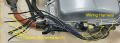
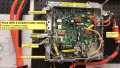 Prius Gen 2 inverter lower casing internals.png 1,920 × 1,080; 3.38 MB
-
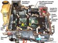
 Prius Gen 2 inverter montage.jpg 1,920 × 1,077; 794 KB
-
 Prius Gen 2 logic board(BluePill-based).jpg 2,032 × 1,248; 615 KB
-
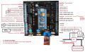
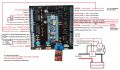 Prius Gen 2 logic board wiring diagram..jpg 2,298 × 1,336; 705 KB
-
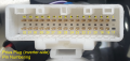 Prius Inverter - Pin Numbering.png 969 × 458; 801 KB
-
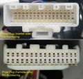 Prius Inverter - Pin Numbering 2.jpg 968 × 919; 141 KB
-
 Prius Inverter Wire Colors 2.jpg 1,024 × 410; 55 KB
-
 Prius Inverter Wire Colors 3.jpg 1,024 × 536; 75 KB
-
 Prius Inverter Wire Colors 4.jpg 1,024 × 605; 108 KB
-
 Prius Inverter Wire Colors 5.jpg 1,024 × 805; 119 KB
-
 Prius Inverter Wire Colors 6.jpg 1,024 × 1,561; 235 KB
-
 Prius Inverter Wire Colors 7.jpg 1,024 × 461; 121 KB
-
 Prius Inverter Wire Colors 8.jpg 1,024 × 395; 45 KB
-
 Prius Inverter Wire Colors 9.jpg 1,024 × 368; 90 KB
-
 Prius ZVW30 D29 A59 Inverter Signals.png 2,104 × 748; 941 KB
-
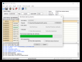 Programming bootloader with ST Link software.png 862 × 645; 53 KB
-
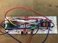 Prototype CAN SoC display.jpg 1,280 × 960; 542 KB
-
 PulseEncoder.jpg 900 × 869; 107 KB
-
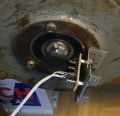
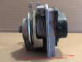
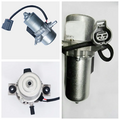 Pump photo.webp 972 × 979; 54 KB
-
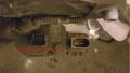
 Push the pins through.jpg 4,032 × 2,268; 6.61 MB
-
 Pwm.png 260 × 117; 11 KB
-
 Pwm circuit hold low.png 540 × 405; 22 KB
-
 Qt 6.4 install only.png 952 × 632; 344 KB
-
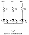 RGB LED common cathode.png 313 × 381; 24 KB
-
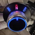
 RND Model B.png 971 × 621; 210 KB
-
 RND Model B schematic.png 798 × 1,285; 445 KB
-
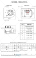
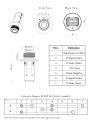
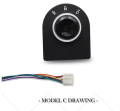 RND Model C.png 769 × 710; 162 KB
-
 RND Model C schematic.png 802 × 1,287; 347 KB
-
 RND switch.jpg 800 × 1,059; 229 KB
-
 RND switch N.jpg 1,024 × 1,024; 124 KB
-
 Rack Pins.jpg 4,032 × 2,268; 1.87 MB
-
 Rear-drive-pinout.png 578 × 412; 90 KB
-
 Rear view.jpg 2,040 × 1,536; 601 KB
-
 Resistor.jpg 2,423 × 1,181; 522 KB
-
 ResolverPicture.jpg 678 × 784; 112 KB
-
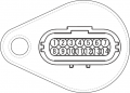
 Resolver Connector MGR.jpg 575 × 412; 29 KB
-
 S-LHD-SOP1 51 Connector X042.png 1,481 × 1,444; 433 KB
-
 S-l1600.jpg 800 × 800; 50 KB
-
 S-l500.jpg 500 × 375; 37 KB
-
 SB-10052449-4313 HVIL Diagnostic Guide 01-1b.png 3,457 × 1,686; 658 KB
-
 SB-10052449-4313 HVIL Diagnostic Guide 08-1b.png 3,090 × 1,600; 1.21 MB
-
 SB-10052449-4313 HVIL Diagnostic Guide 10-1b.png 3,100 × 1,621; 1.19 MB
-
 SBOX.jpg 1,084 × 1,223; 1,006 KB
-
 SN65HVD230 CAN bus transceiver faulty.jpg 604 × 604; 127 KB
-
 SN65HVD230 CAN bus transceiver working.jpg 847 × 847; 199 KB
-
 ST Link Software Settings.png 849 × 627; 51 KB
-
 Schematic current sense board.png 689 × 248; 5 KB
-
 Schematic for OI connection .jpg 1,828 × 3,392; 2.83 MB


.jpg)


