CAN bus with Arduino Due
You can analyse CAN bus traffic using an Arduino Due.
You will need the following:
- An Arduino Due board
- One or two SN65HVD230-based CAN transceivers
- An SPI Micro SD storage module (optional)
Here are the steps:
Configure your Arduino IDE
Download and install the Arduino IDE on your computer
Tools -> Board -> Boards Manager. Type "due" in the search box and install "Arduino SAM Boards (32-bits ARM Cortex-M3)"
Connect your computer to the the "programming" USB port on the Arduino Due board with a USB cable. The Due has two USB ports and they're used for different purposes. More on that later...
Tools -> Port. Make sure your Arduino board is selected
File -> Examples -> 01.Basics -> Blink
Sketch -> Upload
Hopefully you have a blinking light on your Arduino board. This means your IDE is working.
Get CAN working
The Due has two on-board CAN interfaces. However, the board lacks the necessary CAN transceivers to make then useful. You will need to add the transceivers yourself. You can find suitable 3.3V SN65HVD230-based CAN transceivers easily on eBay. They are very cheap. Unfortunately, not all of them work.

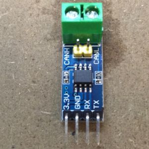
Initially, I tried tiny ones that look like this. They were all faulty.

I tried some bigger ones with screw terminals. These all worked perfectly.
Connect the transceivers to the Due board
The CAN0 interface is on the pins marked CANRX and CANTX
The CAN1 interface is on the pins marked DAC0 (RX) and 53 (TX)
Connect the CAN bus on the two transceivers together (CANL to CANL, CANH to CANH)
Connect your computer to the the "native" USB port on the Arduino Due board with a USB cable and make sure Tools -> Board: "Arduino Due (Native USB port)" is selected.
Tools -> Manage Libraries... Type "due_can" in the search box and install "due_can"
File -> Examples -> due_can -> CAN_ExtendedPingPong
Sketch -> Upload
Tools -> Serial Monitor
If your CAN transceivers are working properly, you should be rewarded with incrementing numbers in the serial monitor window.