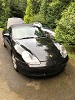
I'm having an interesting issue with the states of the contactors. When I power the system up it appears that all of the contactors are energized simultaneously for a moment, then upon start signal the positive is energized only briefly before opening again. I've made a video to illustrate this and added LEDs to the contactor's power lines to visually see when they're being energized.
- Green is on the negative contactor, which is energized always when the key is on.
- Yellow is Positive Contactor
- Red (on the wall mounted contactor box) is precharge
Has anyone seen this or have any ideas how to troubleshoot further? Thanks!
Contactor woes with LDU board
Re: Contactor woes with LDU board
Post your parameter json and what voltage you’re testing at.
Formerly 92 E30 BMW Cabrio with Tesla power
Re: Contactor woes with LDU board
I haven't been able to get that far yet to configure parameters, I also see this error message. When I go to snapshot.php I see that it's an empty array { "" }.. I attempted to restore parameters from the forum but keep getting the same error. This is the first time setup for this system. Voltage of the HV battery is 368V
- jsonError.PNG (9.67 KiB) Viewed 6621 times
-
Jack Bauer

- Posts: 4007
- Joined: Wed Dec 12, 2018 5:24 pm
- Location: Ireland
- Has thanked: 153 times
- Been thanked: 1139 times
- Contact:
Re: Contactor woes with LDU board
You need to be able to access the web interface before trying to run the motor. I would suggest trying another device.
I'm going to need a hacksaw
Re: Contactor woes with LDU board
I can access the web interface. That’s where the screenshot of the “Power cycle inverter” and json error is coming from. I feel like I’m missing something fundamental. I coaxed the esp8266 module to work by building from source and uploading with Arduino, then uploaded spiffs. I was then able to log in, is there additional configuration I’m missing?
-
Boxster EV
- Posts: 489
- Joined: Fri Jul 26, 2019 9:32 pm
- Location: UK
- Has thanked: 57 times
- Been thanked: 50 times
Re: Contactor woes with LDU board
Not possible to just connect to the inverter over WiFi, open your browser and enter the IP 192.168.4.1 ?
You can then login.
You can then login.
-
muehlpower

- Posts: 807
- Joined: Fri Oct 11, 2019 10:51 am
- Location: Germany Fürstenfeldbruck
- Has thanked: 18 times
- Been thanked: 188 times
Re: Contactor woes with LDU board
I think it's because of the wiring. When switching on and both relays close, the red light in the box is darker, and then becomes brighter when the yellow one is off. That looks like a ground problem.
Re: Contactor woes with LDU board
I took it back apart and verified all my soldering for the connectors just to be sure I didn’t bridge something and miss it. While having the lid off I observed this behavior for the inverter board, (which happens regardless of having the contactors connected or not) Where the red LEDs on the inverter’s boards briefly kick on at power up then go off. Then when the system is powered down they do it again. I’m guessing this isn’t normal behavior? https://youtu.be/VQB01KB49Yc
-
johu

- Site Admin
- Posts: 7182
- Joined: Thu Nov 08, 2018 10:52 pm
- Location: Kassel/Germany
- Has thanked: 552 times
- Been thanked: 1918 times
- Contact:
Re: Contactor woes with LDU board
Power up sequence looks ok on the control board. Gate drive board I have no experience. I'm assuming the red LEDs signal under voltage as you power down.
I assume the contactor click in the background are what you are talking about. Looks like they briefly engage while in boot loader. Can you try mounting a 1-10k resistor across the output FETs (gate to source, i.e. the two actual pins)? Maybe they creep on for some reason.
EDIT:
The positive dropping out must be caused by some other post-start error, like desat or overcurrent - possibly spurious. Let us know the error memory and if you keep having problems with the wifi interface consider using the less beautiful one: https://github.com/jsphuebner/esp8266-web-interface
Support R/D and forum on Patreon: https://patreon.com/openinverter - Subscribe on odysee: https://odysee.com/@openinverter:9
-
johu
- Site Admin
- Posts: 7182
- Joined: Thu Nov 08, 2018 10:52 pm
- Location: Kassel/Germany
- Has thanked: 552 times
- Been thanked: 1918 times
- Contact:
Re: Contactor woes with LDU board
No, between the two pins
Support R/D and forum on Patreon: https://patreon.com/openinverter - Subscribe on odysee: https://odysee.com/@openinverter:9
Re: Contactor woes with LDU board
Hey, that stopped the positive contactor from kicking in at boot 
Now just need to get it to stay on after key switch

Now just need to get it to stay on after key switch
-
johu
- Site Admin
- Posts: 7182
- Joined: Thu Nov 08, 2018 10:52 pm
- Location: Kassel/Germany
- Has thanked: 552 times
- Been thanked: 1918 times
- Contact:
Re: Contactor woes with LDU board
Great. Yes some STMs develop minor damage (static discharge damage) of the output circuitry causing stuff to creep on when the pin isn't explicitly driven low.
I edited my other post, in case you missed it:
The positive dropping out must be caused by some other post-start error, like desat or overcurrent - possibly spurious. Let us know the error memory and if you keep having problems with the wifi interface consider using the less beautiful one: https://github.com/jsphuebner/esp8266-web-interface
Support R/D and forum on Patreon: https://patreon.com/openinverter - Subscribe on odysee: https://odysee.com/@openinverter:9
-
johu
- Site Admin
- Posts: 7182
- Joined: Thu Nov 08, 2018 10:52 pm
- Location: Kassel/Germany
- Has thanked: 552 times
- Been thanked: 1918 times
- Contact:
Re: Contactor woes with LDU board
This story lets me think I should work on the boot loader. I never wanted application specific code in it but I think there is a way around it: I could just reserve another flash page that has pin configuration info. It can start with some magic sequence like 0x55AA55AA. If the magic is not there, the boot loader ignores it.
If it is there it will load pin config info, like "set PC1 to 0".
Alternatively the resistor could always be there but I prefer software to hardware changes
If it is there it will load pin config info, like "set PC1 to 0".
Alternatively the resistor could always be there but I prefer software to hardware changes
Support R/D and forum on Patreon: https://patreon.com/openinverter - Subscribe on odysee: https://odysee.com/@openinverter:9
Re: Contactor woes with LDU board
Hey, always happy to help inspire others!johu wrote: ↑Fri Oct 16, 2020 7:20 am This story lets me think I should work on the boot loader. I never wanted application specific code in it but I think there is a way around it: I could just reserve another flash page that has pin configuration info. It can start with some magic sequence like 0x55AA55AA. If the magic is not there, the boot loader ignores it.
If it is there it will load pin config info, like "set PC1 to 0".
Alternatively the resistor could always be there but I prefer software to hardware changes
Thanks for chiming in, I really do appreciate it. This is the furthest I've been with the board, feeling like I'm relatively close to success here! I flashed the "less beautiful" web interface per your suggestion. This one seems to work every time I boot, which is fantastic as the other kept randomly reverting to "filesystem not found" and requiring SPIFFS upload again for some reason. Anyway, I was able to see with this UI that it is reporting STOP - Overcurrent. I have not flashed firmware to the board or changed any parameters, it's 100% as it came. Any suggestions to remedy this would be welcomed and appreciated. or alternatively I also saw a "remote support" option in the UI, what do you charge for a session? Getting this going would be amazing, been messing with it on and off for weeks.
-
johu
- Site Admin
- Posts: 7182
- Joined: Thu Nov 08, 2018 10:52 pm
- Location: Kassel/Germany
- Has thanked: 552 times
- Been thanked: 1918 times
- Contact:
Re: Contactor woes with LDU board
Did you order on the open inverter shop? In that case it comes with good parameters. Otherwise save these: https://openinverter.org/wiki/Configura ... U_Jon_Volk to a json file and upload that in the parameters section (not update!).
One "Engineering Hour" (https://openinverter.org/shop/index.php ... duct_id=65) is usually enough to solve most problems.
One "Engineering Hour" (https://openinverter.org/shop/index.php ... duct_id=65) is usually enough to solve most problems.
Support R/D and forum on Patreon: https://patreon.com/openinverter - Subscribe on odysee: https://odysee.com/@openinverter:9
Re: Contactor woes with LDU board
Yup, bought from the web shop.
That sounds great, I’ll do just that. Much appreciated
That sounds great, I’ll do just that. Much appreciated
Re: Contactor woes with LDU board
I spent some time searching the forum for others with overcurrent errors and reading the Wiki to make sure I wasn't missing something obvious. Came across the troubleshooting page for LDU board and followed the steps to diagnose there.
When measuring the two test points adjacent to R45 and R58 (no HV, Idle, no start signal), I'm getting approx 1.64V and 1.63V
I set udcsw to 0, saved parameters (actually wouldn't take, I had to edit the previously downloaded JSON and upload to get it to set) and get Overcurrent when I attempt to start. The page indicates this is likely a failure of the inverter, so I tested this by installing the LDU board in another known good inverter and had the same result. Both of these inverters were working fine on the bench previously.
Are there any other measurements I can take on the board to ensure it's in proper working condition?
-
johu
- Site Admin
- Posts: 7182
- Joined: Thu Nov 08, 2018 10:52 pm
- Location: Kassel/Germany
- Has thanked: 552 times
- Been thanked: 1918 times
- Contact:
Re: Contactor woes with LDU board
On the paper I included with the board you will find the pin mapping. Check that all 6 fault pins on the "IGBT DRIVERS" header are high and check for cold solder joins on the connector.
EDIT: you can also check directly at IC10: Pins 1-6 and pin 11 must be high, pin 8 must be low.
Regarding your the boot time contactor click there is now also a software fix: viewtopic.php?f=7&t=1119
EDIT: you can also check directly at IC10: Pins 1-6 and pin 11 must be high, pin 8 must be low.
Regarding your the boot time contactor click there is now also a software fix: viewtopic.php?f=7&t=1119
Support R/D and forum on Patreon: https://patreon.com/openinverter - Subscribe on odysee: https://odysee.com/@openinverter:9
Re: Contactor woes with LDU board
At IC10 I have the following:
1,2: ~5V
3: 3.82V
4: .7V <--
5,6: ~5V
8: ~5V
11: ~5V <--
Looks like 4 and 11 are not as expected.
1,2: ~5V
3: 3.82V
4: .7V <--
5,6: ~5V
8: ~5V
11: ~5V <--
Looks like 4 and 11 are not as expected.
-
johu
- Site Admin
- Posts: 7182
- Joined: Thu Nov 08, 2018 10:52 pm
- Location: Kassel/Germany
- Has thanked: 552 times
- Been thanked: 1918 times
- Contact:
Re: Contactor woes with LDU board
Ok, Pin 4 is "FAULTHC" so high side of the third IGBT module either signals a fault or has a bad connection. Consequently pin 8 is high because not all inputs to the NAND tree are high.
Support R/D and forum on Patreon: https://patreon.com/openinverter - Subscribe on odysee: https://odysee.com/@openinverter:9