Hi all - my first post on this forum. I have an access to salvage parts of an 2015 i3 REX. I was reading the topic of i3 controller hacking from diyelectricar.com. It was said to be continued here but I didn't find any follow-up. What happened to that - is it still working-in-progress?
Anyone been using i3 motor (or batteries/BMS) in their projects?
i3 controller hacking from diyelectriccar.com
-
Scott166
- Posts: 107
- Joined: Thu Jun 04, 2020 12:23 pm
- Location: Dorset, England
- Has thanked: 1 time
- Been thanked: 1 time
Re: i3 controller hacking from diyelectriccar.com
Hi,
I'm using an i3 for my conversion however I'm also looking for the same info as you are.
I'm sure we'll get there in the end!
I'm using an i3 for my conversion however I'm also looking for the same info as you are.
I'm sure we'll get there in the end!
Restoring and converting a Classic Mini, I have mad ideas, semi sensible ideas and NO idea if I’ll ever get it done 
Look me up on YouTube https://youtube.com/channel/UCxmP1hLys6Z5tHZpK5mn6eg to see my progress
Look me up on YouTube https://youtube.com/channel/UCxmP1hLys6Z5tHZpK5mn6eg to see my progress
-
johu

- Site Admin
- Posts: 7182
- Joined: Thu Nov 08, 2018 10:52 pm
- Location: Kassel/Germany
- Has thanked: 552 times
- Been thanked: 1918 times
- Contact:
Re: i3 controller hacking from diyelectriccar.com
I wouldn't mind picking up where Damien left off. Provided i3 inverters are easy to find and cheap?
Support R/D and forum on Patreon: https://patreon.com/openinverter - Subscribe on odysee: https://odysee.com/@openinverter:9
-
Jack Bauer

- Posts: 4007
- Joined: Wed Dec 12, 2018 5:24 pm
- Location: Ireland
- Has thanked: 153 times
- Been thanked: 1139 times
- Contact:
Re: i3 controller hacking from diyelectriccar.com
Not cheap from what I recall but I'll ship mine over as it'll be ages before I get to it:)
I'm going to need a hacksaw
-
golfdubcrazy
- Posts: 88
- Joined: Thu Jan 28, 2021 6:15 pm
- Has thanked: 1 time
- Been thanked: 11 times
Re: i3 controller hacking from diyelectriccar.com
Hi i was interesting in using the i3 inverter module. and iv seen the videos youtube.
would anyone be willing to share the pinout of the igbt control board ?
would anyone be willing to share the pinout of the igbt control board ?
-
Jack Bauer
- Posts: 4007
- Joined: Wed Dec 12, 2018 5:24 pm
- Location: Ireland
- Has thanked: 153 times
- Been thanked: 1139 times
- Contact:
Re: i3 controller hacking from diyelectriccar.com
I'll dig out my notes tomorrow and pop them up on this thread.
I'm going to need a hacksaw
-
arber333
- Posts: 3796
- Joined: Mon Dec 24, 2018 1:37 pm
- Location: Slovenia
- Has thanked: 166 times
- Been thanked: 413 times
- Contact:
Re: i3 controller hacking from diyelectriccar.com
Not exactly cheap in EU!!!
https://rrr.lt/en/used-part/auk124-1232 ... ter+BMW+I3
https://www.proxyparts.com/car-parts-st ... /11851940/
In USA however they seem to be much cheaper.
https://www.ebay.co.uk/itm/2014-15-16-1 ... SwqWFfUQcY
https://rrr.lt/en/used-part/auk124-1232 ... ter+BMW+I3
https://www.proxyparts.com/car-parts-st ... /11851940/
In USA however they seem to be much cheaper.
https://www.ebay.co.uk/itm/2014-15-16-1 ... SwqWFfUQcY
-
johu
- Site Admin
- Posts: 7182
- Joined: Thu Nov 08, 2018 10:52 pm
- Location: Kassel/Germany
- Has thanked: 552 times
- Been thanked: 1918 times
- Contact:
Re: i3 controller hacking from diyelectriccar.com
Is that always the same part? Ah maybe one with Rex and one without?
Support R/D and forum on Patreon: https://patreon.com/openinverter - Subscribe on odysee: https://odysee.com/@openinverter:9
-
FJ3422

- Posts: 122
- Joined: Fri Jul 10, 2020 9:55 am
- Location: Netherlands
- Has thanked: 13 times
- Been thanked: 3 times
Re: i3 controller hacking from diyelectriccar.com
AFAIK - There are two parts.
REME - Small inverter for the optional range-extender (650cc gasoline with 25kW generator). Used to charge the battery with up to 25kW and to start the engine.
Disassembly video:
The inverter is this part. I don't know if the hardware is different for versions with / without REX, at least the partnumbers are different.
REME - Small inverter for the optional range-extender (650cc gasoline with 25kW generator). Used to charge the battery with up to 25kW and to start the engine.
The inverter is this part. I don't know if the hardware is different for versions with / without REX, at least the partnumbers are different.
-
Jack Bauer
- Posts: 4007
- Joined: Wed Dec 12, 2018 5:24 pm
- Location: Ireland
- Has thanked: 153 times
- Been thanked: 1139 times
- Contact:
Re: i3 controller hacking from diyelectriccar.com
Notes from my original investigations and running with Lebowski. Inverter will be on its way to Johannes shortly:)
- Attachments
-
-
-
-
-
-
I'm going to need a hacksaw
-
golfdubcrazy
- Posts: 88
- Joined: Thu Jan 28, 2021 6:15 pm
- Has thanked: 1 time
- Been thanked: 11 times
Re: i3 controller hacking from diyelectriccar.com
Thanks for that  i will post my progress once i start the teardown
-
golfdubcrazy
- Posts: 88
- Joined: Thu Jan 28, 2021 6:15 pm
- Has thanked: 1 time
- Been thanked: 11 times
Re: i3 controller hacking from diyelectriccar.com
Hi Can i just check this is correct to your notes. and can i confirm what LEM is?
sorry its hard to sometimes read other peoples notes and i rather not blow up the IGBTS
Pin No I/O Description Notes
1
2 i 32V in
3 i 32V in
4 i IGBT A HI
5 i IGBT A LOW
6
7
8
9
10 i IGBT B HI
11 i IGBT B LOW
12 i IGBT C HI
13 i IGBT C LOW
14
15
16
17
18 O Current Sense C
19 O Current Sense B
20 O Current Sense A
21 GND
22 GND
23
24
25
26 GND
27 GND
28 GND
29 GND
30 GND
31 GND
32 GND
33 5V
34 5V
35 I IGBT PSU 12V on
36
37 i 5V LEM
38 GND
39 GND
40 GND
-
jnsaff

- Posts: 179
- Joined: Fri Oct 18, 2019 7:42 am
- Location: Tallinn, Estonia
- Has thanked: 3 times
- Been thanked: 8 times
Re: i3 controller hacking from diyelectriccar.com
Theres this one here for about 62 euros with obvious damage but maybe a cheap place to start https://www.xdalys.lt/en/bmw-i3-inverte ... 350_others
-
golfdubcrazy
- Posts: 88
- Joined: Thu Jan 28, 2021 6:15 pm
- Has thanked: 1 time
- Been thanked: 11 times
Re: i3 controller hacking from diyelectriccar.com
Thanks unfortunately i think this is the charging unit not the inverter.jnsaff wrote: ↑Sat Jan 30, 2021 11:21 am Theres this one here for about 62 euros with obvious damage but maybe a cheap place to start https://www.xdalys.lt/en/bmw-i3-inverte ... 350_others
Bmw went about the design of the i3 high voltage system in an interesting manner.
having a charging unit, main inverter, and mini inverter (for REX)
-
golfdubcrazy
- Posts: 88
- Joined: Thu Jan 28, 2021 6:15 pm
- Has thanked: 1 time
- Been thanked: 11 times
Re: i3 controller hacking from diyelectriccar.com
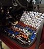
Got my inverter today and started the teardown
got to the IGBT board and started probing the lines, figured out a few more pins. the IGBT has 3 temp sensors but couldnt seem to find where that signal leads to.
looking at the connector on the board looks like
https://www.mouser.co.uk/ProductDetail/ ... YDcw%3D%3D
still need to give it a proper measure but hopefully its correct
Pin No I/O Description Notes
1
2 i 32V in
3 i 32V in
4 i IGBT A HI
5 i IGBT A LOW
6
7
8
9
10 i IGBT B HI
11 i IGBT B LOW
12 i IGBT C HI
13 i IGBT C LOW
14
15
16 O IGBT DRIVER UVW Upper Ready
17 O IGBT DRIVER UVW Lower Ready
18 O Current Sense C Signal
19 O Current Sense B Signal
20 O Current Sense A Signal
21 GND Switching Mosfets ?
22 GND Switching Mosfets ?
23
24
25
26 GND IGBT Driver ground
27 GND IGBT Driver ground
28 GND IGBT Driver ground
29 GND IGBT Driver ground
30 GND IGBT Driver ground
31 GND IGBT Driver ground
32 GND IGBT Driver ground
33 5V IGBT Driver Power
34 5V IGBT Driver Power
35 I IGBT PSU 12V on
36 O IGBT Driver Fault
37 i 5V LEM Current sensor Power
38 GND Current sensor Ground
39 GND Current sensor Ground
40 GND Current sensor Ground
21 22 23 24 25 26 27 28 29 30 31 32 33 34 35 36 37 38 39 40
1 2 3 4 5 6 7 8 9 10 11 12 13 14 15 16 17 18 19 20
- Attachments
-
-
-
-
-
Hans Gustafsson
- Posts: 20
- Joined: Tue Feb 09, 2021 9:13 am
- Location: Sweden
- Been thanked: 1 time
Re: i3 controller hacking from diyelectriccar.com
Thanks Jack for the info on the revolver. I am also very interested in this project. I have a bmw i3 engine in a Renault grand senice. Right now I'm putting a Bamocar d3 400/400 inverter on it, but an original BMW inverter would be better and more powerful.
-
Hans Gustafsson
- Posts: 20
- Joined: Tue Feb 09, 2021 9:13 am
- Location: Sweden
- Been thanked: 1 time
Re: i3 controller hacking from diyelectriccar.com
Here is a description of inverter for those interested. If you use "Google translate", it is easy to read, for non Hungarians. Written by Péter Varsányi,
https://villanyautosok.hu/2018/02/05/bm ... r-javitas/
https://villanyautosok.hu/2018/02/05/bm ... r-javitas/
Re: i3 controller hacking from diyelectriccar.com
Oh wow, just realized there's been a lot of discussion on this topic after all! That is so great!
Not sure if I have skills to help on hacking, but I have an access to an inverter if needed.
I was planning to use Tesla SDU in my conversion but it may be a bit overkill in a 1975 Audi. i3 motor and gearbox would also mechanically fit better.
Not sure if I have skills to help on hacking, but I have an access to an inverter if needed.
I was planning to use Tesla SDU in my conversion but it may be a bit overkill in a 1975 Audi. i3 motor and gearbox would also mechanically fit better.
Re: i3 controller hacking from diyelectriccar.com
This part is actually from the car that we dismantled. I can arrange good discounts on parts of this car if someone is interestedarber333 wrote: ↑Thu Jan 28, 2021 8:51 pm Not exactly cheap in EU!!!
https://rrr.lt/en/used-part/auk124-1232 ... ter+BMW+I3
-
FJ3422
- Posts: 122
- Joined: Fri Jul 10, 2020 9:55 am
- Location: Netherlands
- Has thanked: 13 times
- Been thanked: 3 times
Re: i3 controller hacking from diyelectriccar.com
The REME (small 25kW REX inverter) could be a nice option for small cars & motorcycle conversions. Looking at the video, it has a quite basic controlPCB with no weird connectors and an easy interfaceable IGBT-driver board without SPI (https://www.infineon.com/cms/en/product ... 020i12-f2/).
Does anyone know which IGBT's are used in this inverter ? If it's capable of about 60-70kW at 400V, I have a purpose for it, will buy one and try to convert it.
Does anyone know which IGBT's are used in this inverter ? If it's capable of about 60-70kW at 400V, I have a purpose for it, will buy one and try to convert it.
-
johu
- Site Admin
- Posts: 7182
- Joined: Thu Nov 08, 2018 10:52 pm
- Location: Kassel/Germany
- Has thanked: 552 times
- Been thanked: 1918 times
- Contact:
Re: i3 controller hacking from diyelectriccar.com
Got mail from Damien  With the existing notes and the jumper cables he sent along it took me 10 minutes to fire up the inverter.
It draws 2.3W from the 32V line in idle and 10.7W when running at 8.8 kHz. 5V for openinverter board and BMW logic are provided by my USB hub, so apparently not much draw there.
Despite this being the same power module as in the Leaf 3 inverter (Infineon FS800R07) the deadtime requirement seems much lower. When run with 800 ns it draws 70 mA from 50V and with 2.5us it draws 66 mA. Will investigate further, maybe they use smaller gate resistors. There is certainly no electronic dead time guard, because setting deadtime 0 sends the lab supply into current limit.
The openinverter board almost bolts onto the 4 screw holes on the capacitor cover According to Damien the cover is pretty bulky so there should be enough room for an adapter board and a mainboard on top.
It draws 2.3W from the 32V line in idle and 10.7W when running at 8.8 kHz. 5V for openinverter board and BMW logic are provided by my USB hub, so apparently not much draw there.
Despite this being the same power module as in the Leaf 3 inverter (Infineon FS800R07) the deadtime requirement seems much lower. When run with 800 ns it draws 70 mA from 50V and with 2.5us it draws 66 mA. Will investigate further, maybe they use smaller gate resistors. There is certainly no electronic dead time guard, because setting deadtime 0 sends the lab supply into current limit.
The openinverter board almost bolts onto the 4 screw holes on the capacitor cover
Support R/D and forum on Patreon: https://patreon.com/openinverter - Subscribe on odysee: https://odysee.com/@openinverter:9
-
johu
- Site Admin
- Posts: 7182
- Joined: Thu Nov 08, 2018 10:52 pm
- Location: Kassel/Germany
- Has thanked: 552 times
- Been thanked: 1918 times
- Contact:
Re: i3 controller hacking from diyelectriccar.com
Oh, forgot to ask. Whats the purpose of pin 35? When trying to feed it 12V it seems to be pretty much a short. Just leaving it open allows operating the inverter though, so might not be important.
Support R/D and forum on Patreon: https://patreon.com/openinverter - Subscribe on odysee: https://odysee.com/@openinverter:9
-
johu
- Site Admin
- Posts: 7182
- Joined: Thu Nov 08, 2018 10:52 pm
- Location: Kassel/Germany
- Has thanked: 552 times
- Been thanked: 1918 times
- Contact:
Re: i3 controller hacking from diyelectriccar.com
Now, I tried to find a nice analog bus voltage and temperature signal. Not so, they chose to digitally isolate in form of a ADS7955 ADC and ISO7241 digital isolator. Bus voltage sensing itself is 1V/100V resistor chain.
So now I can attempt to use it or just put some analog isolator on the adapter board.
So now I can attempt to use it or just put some analog isolator on the adapter board.
- Attachments
-
Support R/D and forum on Patreon: https://patreon.com/openinverter - Subscribe on odysee: https://odysee.com/@openinverter:9
-
johu
- Site Admin
- Posts: 7182
- Joined: Thu Nov 08, 2018 10:52 pm
- Location: Kassel/Germany
- Has thanked: 552 times
- Been thanked: 1918 times
- Contact:
Re: i3 controller hacking from diyelectriccar.com
So UDC is on CH5 and 3 temperatures are on channels CH0-CH2
Using the ADC is pretty simple, It is just sent 16 bits with instructions and returns the value resulting from the second-to-last instruction. I could just resort to bit-banging SPI via udc/tmphs and some general output pin. Or I could place an attiny or something on the adapter board to convert the digital data stream back to analog.
EDIT: will just add to the existing pinmap:
1
2 i 32V in
3 i 32V in
4 i IGBT A HI
5 i IGBT A LOW
6 /CS (ADC)
7 SDI
8 SDO
9 SCK
10 i IGBT B HI
11 i IGBT B LOW
12 i IGBT C HI
13 i IGBT C LOW
14
15
16 O IGBT DRIVER UVW Upper Ready
17 O IGBT DRIVER UVW Lower Ready
18 O Current Sense C Signal
19 O Current Sense B Signal
20 O Current Sense A Signal
21 GND Switching Mosfets ?
22 GND Switching Mosfets ?
23
24
25
26 GND IGBT Driver ground
27 GND IGBT Driver ground
28 GND IGBT Driver ground
29 GND IGBT Driver ground
30 GND IGBT Driver ground
31 GND IGBT Driver ground
32 GND IGBT Driver ground
33 5V IGBT Driver Power
34 5V IGBT Driver Power
35 I IGBT PSU 12V on
36 O IGBT Driver Fault
37 i 5V LEM Current sensor Power
38 GND Current sensor Ground
39 GND Current sensor Ground
40 GND Current sensor Ground
21 22 23 24 25 26 27 28 29 30 31 32 33 34 35 36 37 38 39 40
1 2 3 4 5 6 7 8 9 10 11 12 13 14 15 16 17 18 19 20
There is also another isolator coupled to some mystery ST chip (it says 78387).
Support R/D and forum on Patreon: https://patreon.com/openinverter - Subscribe on odysee: https://odysee.com/@openinverter:9
-
Jack Bauer
- Posts: 4007
- Joined: Wed Dec 12, 2018 5:24 pm
- Location: Ireland
- Has thanked: 153 times
- Been thanked: 1139 times
- Contact:
Re: i3 controller hacking from diyelectriccar.com
Nice find. Obviously this is why they needed the tricore mcu:)
edit: my mistake, it has 2 tricore mcus.
edit: my mistake, it has 2 tricore mcus.
I'm going to need a hacksaw