Leaf EM57 resolver wired directly to Johannes board (RES pins) — angle stuck at 0°
System
Motor: Nissan Leaf EM57
Controller: OpenInverter Johannes Leaf board
Firmware: 5.xx.R-FOC
Resolver is connected directly to the RES_R1/R2/S1–S4 pins on the Johannes board (not routed through the OEM inverter PCB).
---
Problem
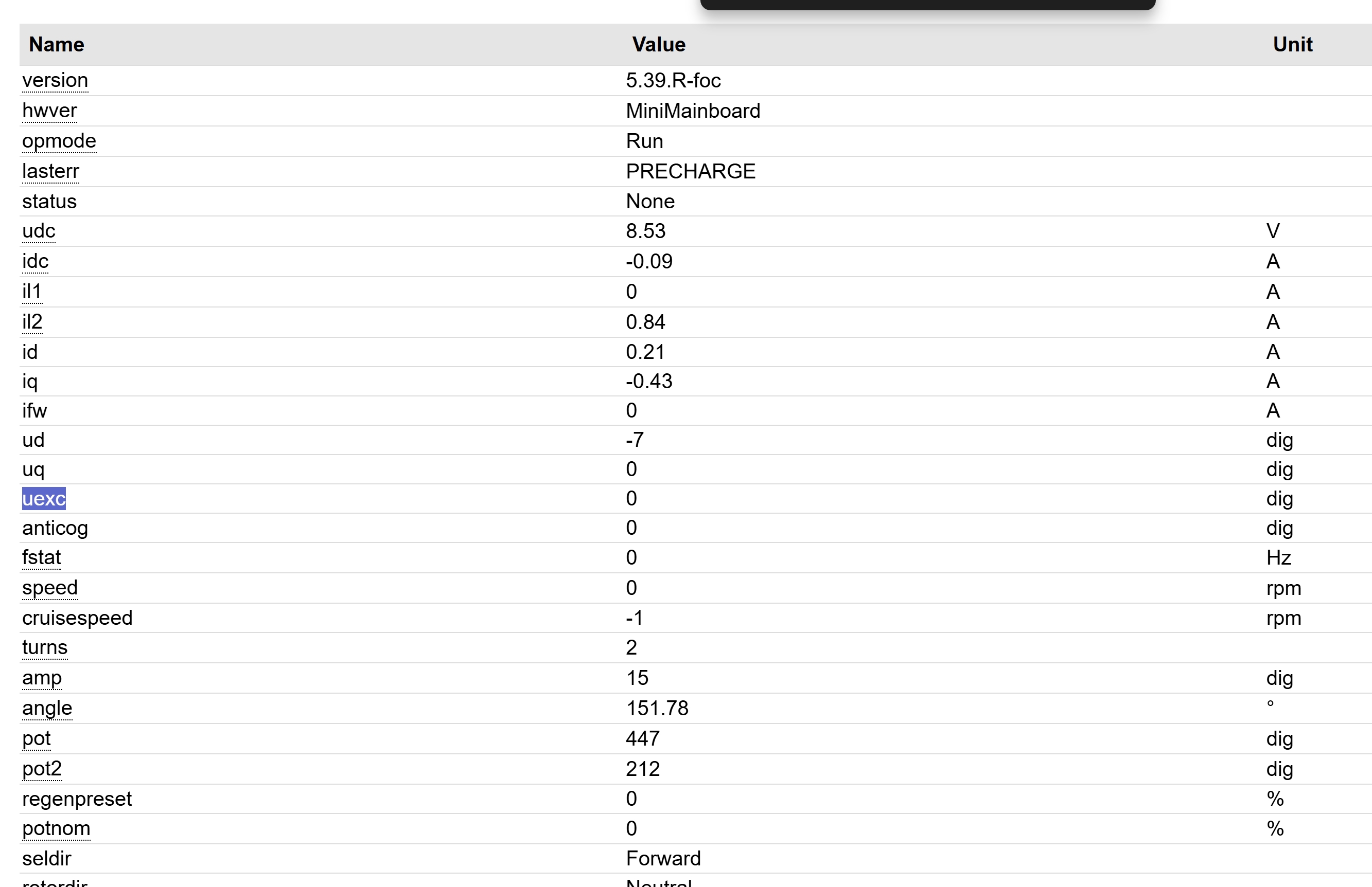
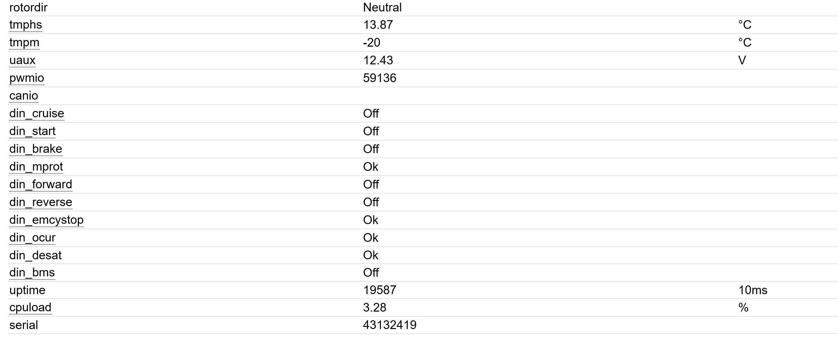
Resolver angle shown in Spot Values remains 0° even when the shaft is rotated by hand.
FOC firmware is running and encmode is set to resolver.
---
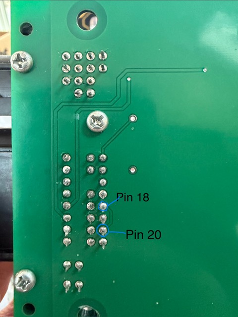
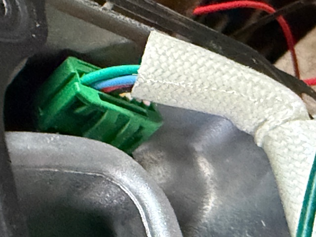
Resolver Connector Pinout
Small 8-pin resolver connector on the motor (not the wiring harness)
Code: Select all
				  Top
Away from Motor			1	5	Motor side
				2	6
			clip	3	7
				4	8
				Bottom
Code: Select all
top 1 2 3 4 5 7 8 9 bottom
Using continuity testing between the internal resolver terminal strip and the external connector I mapped the wires as follows:
- Pin 1 – Green
- Pin 2 – Blue
- Pin 3 – Red
- Pin 4 – Black
- Pin 5 – Yellow
- Pin 6 – White
- Pin 7 – Gray
- Pin 8 – Pink
Coil Identification
Measured resistances with resolver disconnected:
- Red ↔ Pink = 10.6 Ω
- White ↔ Gray = 25 Ω
- Yellow ↔ Black = 25 Ω
- Green ↔ Blue = temperature sensor
Current Wiring to Johannes Board
Code: Select all
RES_R1 → Red
RES_R2 → Pink

RES_S1 → White
RES_S2 → Gray

RES_S3 → Yellow
RES_S4 → Black
---
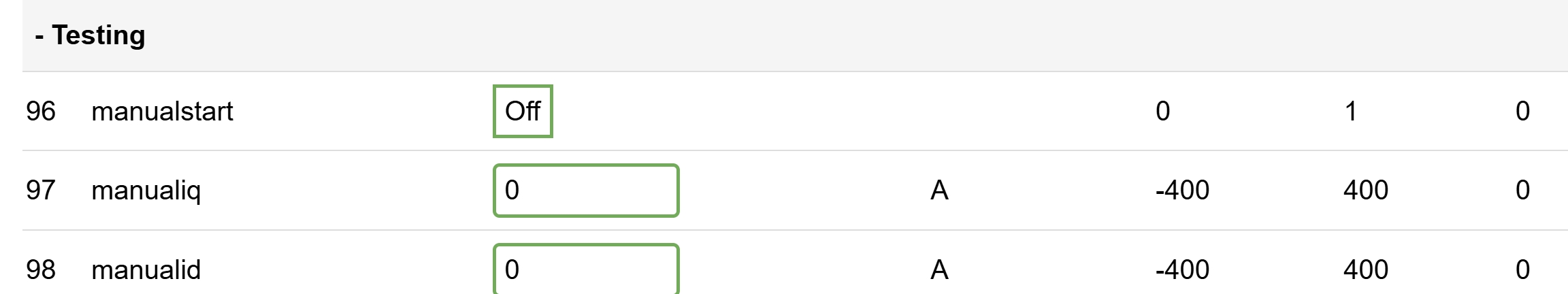
Firmware Settings
Code: Select all
encmode = Resolver
respolepairs = 4
pinswap = None
---
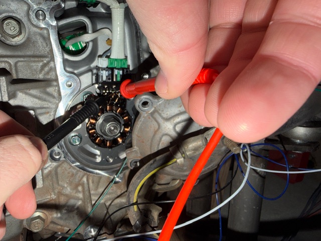
Measurements
Resolver connected.
Meter set to AC volts.
Across excitation pair:
Code: Select all
Red ↔ Pink ≈ 0V AC
Code: Select all
White ↔ Gray ≈ 0–0.1V AC
Yellow ↔ Black ≈ 0–0.1V AC
If I reference the meter to another resolver wire I can see some AC voltage, which suggests the excitation signal may be floating.
---
Connector Verification
- Resolver connector fully seated and locked
- Continuity verified between internal resolver terminal strip and external connector pins
- Coil resistances verified multiple times
Questions
- Should resolver excitation be measurable across RES_R1 ↔ RES_R2 with a standard multimeter?
- Is there any parameter required to enable resolver excitation beyond encmode = resolver?
- Is it expected that excitation may not be visible with a standard meter due to frequency?
- Is wiring directly to the RES pins supported, or must the resolver route through the inverter PCB?
Attachments
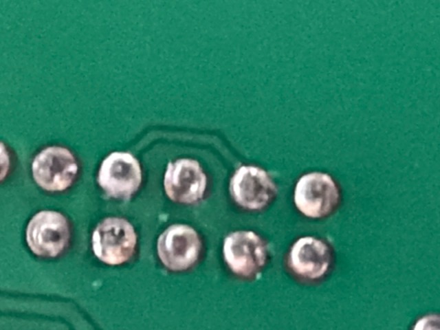
Photos of:
- Resolver internal wiring
- Resolver connector pin mapping