m.art.y wrote: ↑Sat Dec 12, 2020 5:50 pm
I measured again with encoder signals disconnected from the gen3 inverter and across encoder ground and the signals I still get something like 4.8 v (possibly a touch higher this is just what I caught with multimeter.
Would you be able to show how to wire that resistor divider as I am really struggling..

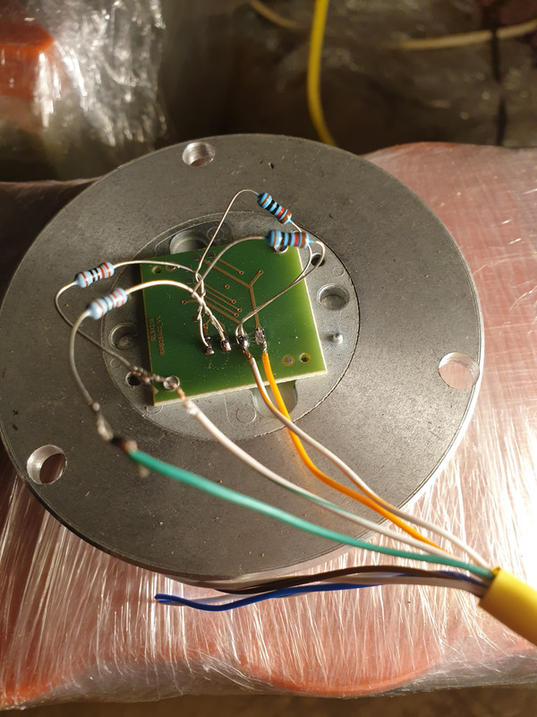
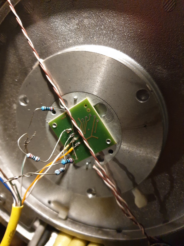
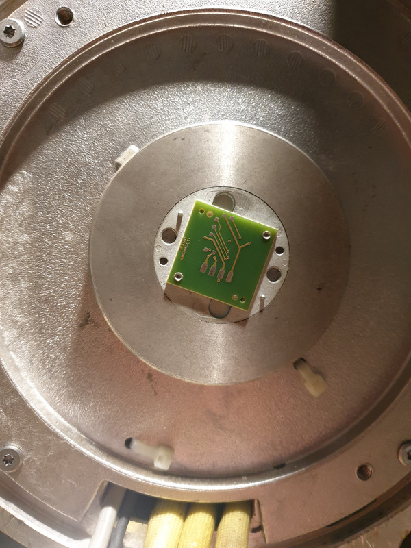
What the #"$ are you doing with encoder pins! They should just have soldered wires directly. Remove those resistors because they are not helping. If you have to do anything to the circuit you must do it as close to input(inverter) as possible.
1. Now from your measurement i think you measured signal between RLS encoder GND and Sin/Cos signals and got 1V or so yes? That is good.
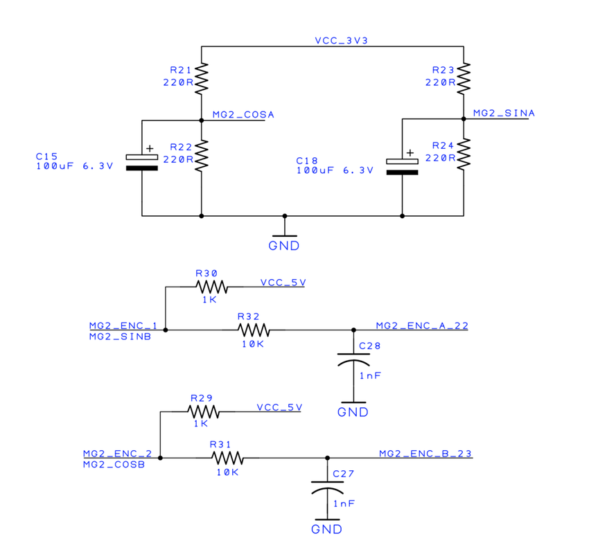
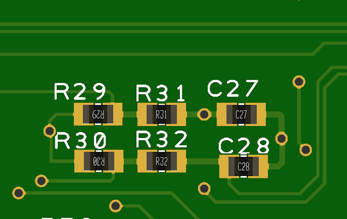
2. If i understend correctly you also measured signals Enc A/Enc B to GND on inverter circuit without RLS connected? If you got 4,8V that means you have pullup resistors on them inputs. There should be 10K resistors on input lines. Try to find them. From schematic for MG2 i see they are R130 and R129 and their value seems 1K to me which is quite high!
Just remove them and use circuit direct.
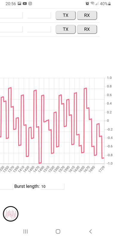
EDIT: Damn, now i forgot that ENC A and B pins AD cant measure negative values! Yes you need to provide correct pullup divider so that Sin/Cos signal will drain pins Enc A and B approximately to 0V when signal will be at negative -1.1V. This means you need approximately 2.2V divider. There is already 10K on the line. Now you need to provide 6K8 or 7K6 divider to get signal to 2V.
What i would do is remove those R130/R129. Then i would put 10K resistors in their place. This is actually not needed because i see 12mA drain capability on RLS chip and 1K pullup provides less power. So this step is not needed actually...
Then i would add 6K8 resistor across 1nF caps so you would get 2.2V signal. You may have to use 7K6 or 8K2 resistor to get correct voltage...
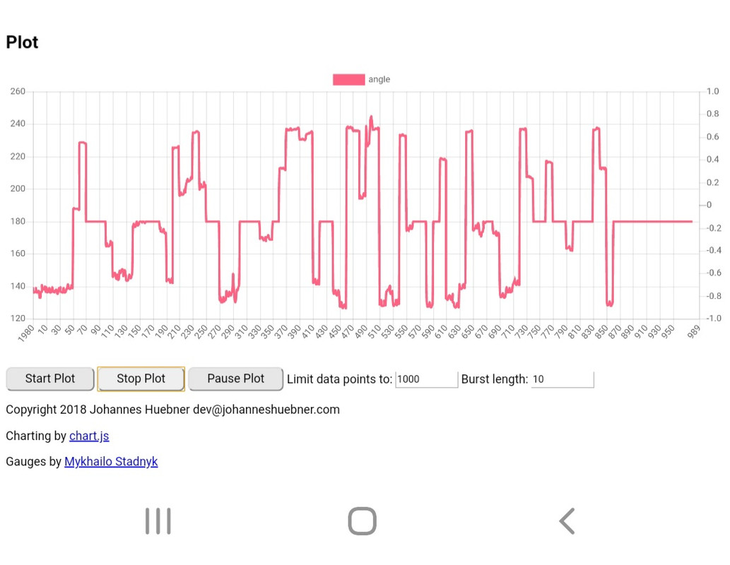
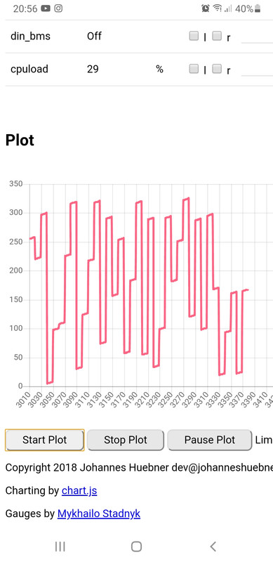
Now try to measure your circuit when you rotate rotor. Should move from 0V to 2.2V approximately.
Caution to others, i think we need to put something to Wiki. Like "In case you use Sin/Cos circuit with Toyota Gen3 board add 6K8 pulldown resistors across 1nF caps." Just to eliminate future mishaps.
A


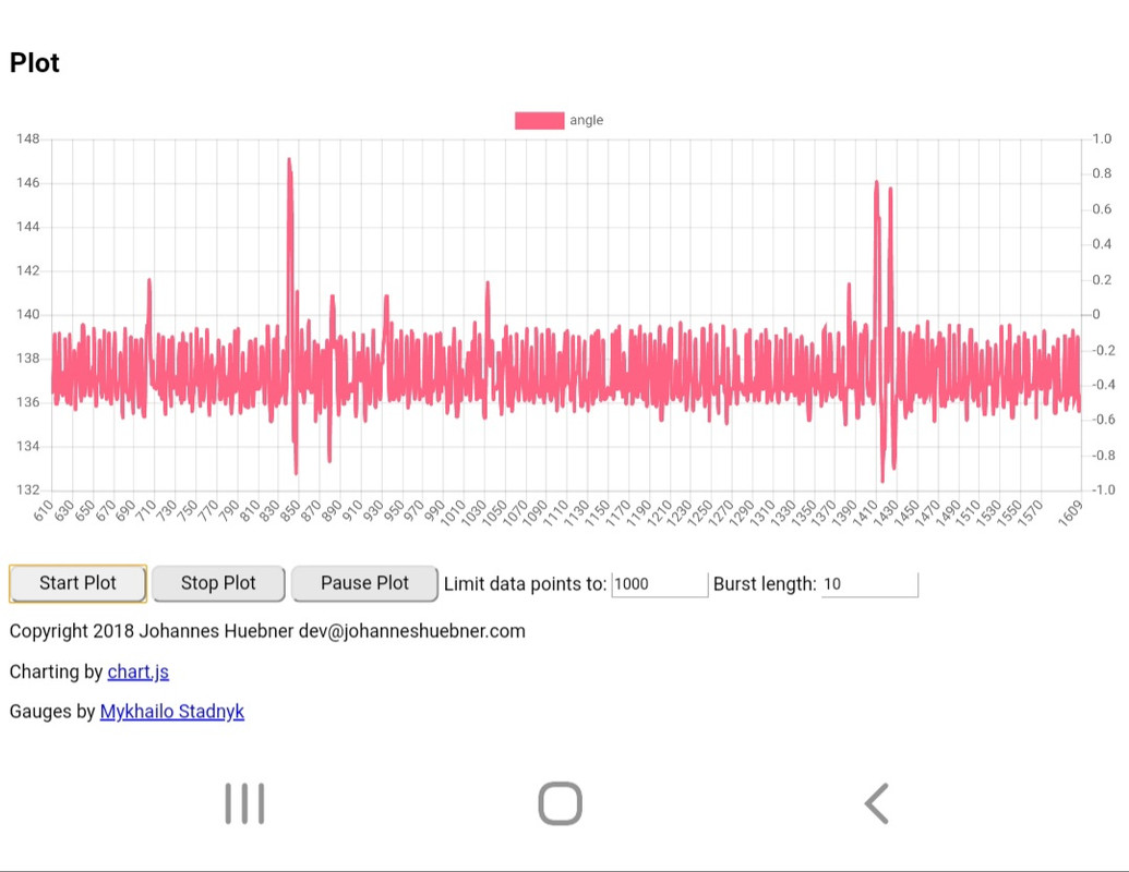
 Something obviously happened for it to go from some sort of reading to none. I did not use shielded cable for testing yet. Could it have been affected by the spinning of the motor with sine firmware?