Chevrolet Volt Charger: Difference between revisions
m Fixed category tag. |
Categories |
||
| (3 intermediate revisions by 3 users not shown) | |||
| Line 1: | Line 1: | ||
This unit is CAN controlled also. It is actually two chargers in one box. One module charges 12V battery up to 30A worth. Second module is HV charger and it can operate from 200V up to 420Vdc. Usually it provides 8A for charging the main battery. | This unit is CAN controlled also. It is actually two chargers in one box. One module charges 12V battery up to 30A worth. Second module is HV charger and it can operate from 200V up to 420Vdc. Usually it provides 8A for charging the main battery. | ||
[[File:New-Doc-2018-12-26-20.25.04 1.jpg|thumb]] | [[File:New-Doc-2018-12-26-20.25.04 1.jpg|thumb]] | ||
First we need to connect to 12V battery. Second connector provides control voltage and interlock in case of EVSE malfunction. Note charger has two CAN bus lines. We only utilise the first one as seen from the | First we need to connect to 12V battery. Second connector provides control voltage and interlock in case of EVSE malfunction. Note charger has two CAN bus lines. We only utilise the first one as seen from the sketch. Drawn is connector from charger side. | ||
The Lear operates CAN at 500Kbps. | The Lear operates CAN at 500Kbps. | ||
Select which of the charger modules you | Select which of the charger modules you wish to operate. Only one msg is sent for heartbeat, do not send all three messages! | ||
Address DLC Data0 Data1 Data2 Data3 | Address DLC Data0 Data1 Data2 Data3 | ||
| Line 13: | Line 13: | ||
0x30E 1 0x02 Turn on HV Charging | 0x30E 1 0x02 Turn on HV Charging | ||
[[File:Volt gen1 charger Control1.png|thumb]] | |||
0x30E 1 0x03 Turn on aux12vdc and turn on HV Charging | 0x30E 1 0x03 Turn on aux12vdc and turn on HV Charging | ||
| Line 21: | Line 21: | ||
0x304 4 0x40 0xA0 0x03 0x20 Charge at 8amps to 400.0vdc | 0x304 4 0x40 0xA0 0x03 0x20 Charge at 8amps to 400.0vdc | ||
[[File:Volt gen1 charger Control2.png|thumb]] | |||
[[File:Volt gen1 charger DC.png|thumb]] | |||
This is sent at 500ms interval | This is sent at 500ms interval | ||
Address 0x304 Data0 is an unknown at present, but seem to be 40 or 48 in the Volt. | Address 0x304 Data0 is an unknown at present, but seem to be 40 or 48 in the Volt. | ||
[[File:Volt gen1 charger AC.png|thumb]] | |||
Address 0x304 Data1 is the current commanded, convert to decimal and divide by 20. | Address 0x304 Data1 is the current commanded, convert to decimal and divide by 20. | ||
| Line 46: | Line 47: | ||
Charger really needs liquid cooling as it gets hot quickly when charging at 8A. | Charger really needs liquid cooling as it gets hot quickly when charging at 8A. | ||
[[File:Ampera Volt gen1 charger.jpg|thumb]] | [[File:Ampera Volt gen1 charger.jpg|thumb]] | ||
[[Category:Chevrolet]] [[Category:Opel]] [[Category:Charger]] | |||
Latest revision as of 16:37, 20 December 2024
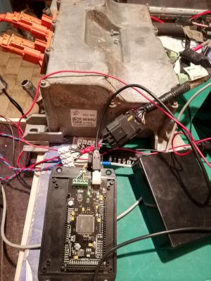
This unit is CAN controlled also. It is actually two chargers in one box. One module charges 12V battery up to 30A worth. Second module is HV charger and it can operate from 200V up to 420Vdc. Usually it provides 8A for charging the main battery.
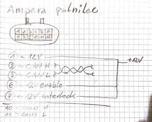
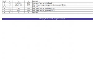
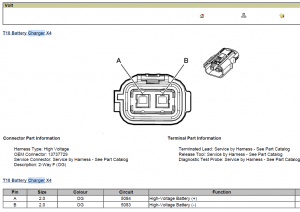
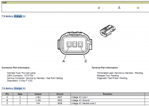
First we need to connect to 12V battery. Second connector provides control voltage and interlock in case of EVSE malfunction. Note charger has two CAN bus lines. We only utilise the first one as seen from the sketch. Drawn is connector from charger side.
The Lear operates CAN at 500Kbps.
Select which of the charger modules you wish to operate. Only one msg is sent for heartbeat, do not send all three messages!
Address DLC Data0 Data1 Data2 Data3
0x30E 1 0x01 Turn on aux12vdc
0x30E 1 0x02 Turn on HV Charging
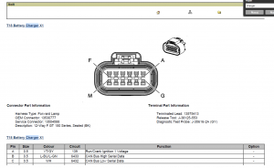
0x30E 1 0x03 Turn on aux12vdc and turn on HV Charging
This message is sent at 30ms interval
Then send command line.
0x304 4 0x40 0xA0 0x03 0x20 Charge at 8amps to 400.0vdc
This is sent at 500ms interval
Address 0x304 Data0 is an unknown at present, but seem to be 40 or 48 in the Volt.
Address 0x304 Data1 is the current commanded, convert to decimal and divide by 20.
Address 0x304 Data2 first 2 bits are MSB of the voltage command.
Address 0x304 Data3 byte is the LSB of the voltage command. Then MSB LSB is divided by 2.
Example:
Data1 is A0(hex) which is 160 decimal. Divided by 20 is 8 and that is the commanded current.
Data2 is 03(hex) and Data3 is 20(hex) which is 0320(hex) equals 800(decimal) divided by 2 is 400vdc.
Charging at 10A and to 410V
0x304 4 0x40 0xC8 0x03 0x34
Current measurement is in returned message 0x212 data byte0 and data byte1 as a 16 bit integer, then divide that by 158 to read actual output current.
Charger really needs liquid cooling as it gets hot quickly when charging at 8A.
