Leaf stack with zombiverter: Difference between revisions
GregFordyce (talk | contribs) |
|||
| (20 intermediate revisions by 6 users not shown) | |||
| Line 1: | Line 1: | ||
<nowiki>*</nowiki>this page is a work in progress and may not be fully accurate or up to date. | <nowiki>*</nowiki>this page is a work in progress and may not be fully accurate or up to date. | ||
| Line 4: | Line 6: | ||
The full leaf stack ( motor/inverter, pdm (charger, dcdc, hvjb)) can be controlled with the zombieverter VCU. | The full leaf stack ( motor/inverter, pdm (charger, dcdc, hvjb)) can be controlled with the zombieverter VCU. | ||
All you need is 12v and CANbus. | All you need is 12v+, enable, and CANbus. ''<u>Note: You still need the OEM connection between the Inverter and Motor Temperature sensors and Resolver for things to function.</u>'' | ||
''As of software release [https://github.com/damienmaguire/Stm32-vcu/releases/tag/2.20a V2.20A,] the IVT shunt used for UDC data is no longer required for precharge.'' | |||
''The leaf Inverter itself'' can supply UDC data for precharge (set the Shunt Type = 0) | |||
the PDM is not needed for UDC data. | |||
The leaf motor and inverter do not require the PDM to run with the zombieverter, or for UDC measurements. | |||
== Wiring == | == Wiring == | ||
[[File:Zombi-leaf-wiringv3.jpg|thumb|568x568px]] | |||
=== Wiring the zombiverter to the leaf harness === | |||
===== Pinout ===== | |||
{| class="wikitable" | |||
! colspan="2" |Description | |||
!Zombieverter Pin | |||
!PDM pin | |||
!inverter pin | |||
!inverter gen3 pin | |||
!battery pin | |||
|- | |||
| +12V | |||
|Permanent 12v+ | |||
|56 | |||
|18 | |||
|46, 48 | |||
|1, 6 | |||
|5, 11, 14, 17 | |||
|- | |||
|Gnd | |||
|permanent 12v - | |||
|55 | |||
|pdm case | |||
|47, 49 | |||
|4, 10 | |||
|6, 7, 8 | |||
|- | |||
|Fwd signal | |||
|Forward | |||
|54 | |||
| | |||
| | |||
| | |||
| | |||
|- | |||
|Rev signal | |||
|Reverse | |||
|53 | |||
| | |||
| | |||
| | |||
| | |||
|- | |||
|momentary 12V | |||
|Start signal | |||
|52 | |||
| | |||
| | |||
| | |||
| | |||
|- | |||
|Brake signal | |||
|Brake Input | |||
|49 | |||
| | |||
| | |||
| | |||
| | |||
|- | |||
| +5V | |||
|Throttle | |||
|48 | |||
| | |||
| | |||
| | |||
| | |||
|- | |||
|Throttle signal 1 | |||
|Throttle signal 1 | |||
|47 | |||
| | |||
| | |||
| | |||
| | |||
|- | |||
|Throttle signal 2 | |||
|Throttle signal 2 | |||
|46 | |||
| | |||
| | |||
| | |||
| | |||
|- | |||
|Throttle Gnd | |||
|Throttle Gnd | |||
|45 | |||
| | |||
| | |||
| | |||
| | |||
|- | |||
|Precharge Contactor LS Switch | |||
|Negative lead from precharge contactor | |||
|34 | |||
| | |||
| | |||
| | |||
|10 | |||
|- | |||
|Main Contactor LS Switch | |||
|Negative lead from main contactor | |||
|33 | |||
| | |||
| | |||
| | |||
|16 | |||
|- | |||
|enable relay | |||
|switches enable relay | |||
|32 | |||
|16 | |||
|42 | |||
|18 | |||
|31 | |||
|- | |||
|Neg Contactor LS Switch | |||
|Negative lead from negative contactor | |||
|31 | |||
| | |||
| | |||
| | |||
|13 | |||
|- | |||
|CANEXTH | |||
|Can 1 High | |||
|28 | |||
|27 | |||
|14 | |||
|5 | |||
|1 | |||
|- | |||
|CANEXTL | |||
|Can 1 Low | |||
|27 | |||
|11 | |||
|15 | |||
|11 | |||
|2 | |||
|- | |||
|T15 | |||
|Ignition 12V in | |||
|15 | |||
| | |||
| | |||
| | |||
|4 | |||
|- | |||
|proximity pilot | |||
|pp for charge port | |||
| | |||
|29 | |||
| | |||
| | |||
| | |||
|- | |||
|control pilot | |||
|cp for charge port | |||
| | |||
|30 | |||
| | |||
| | |||
| | |||
|} | |||
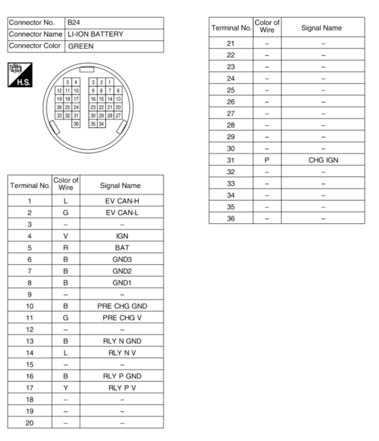
[[File:Leaf Inverter connections.png|left|thumb|818x818px|Leaf Inverter terminal layout and physical values for signals]] | |||
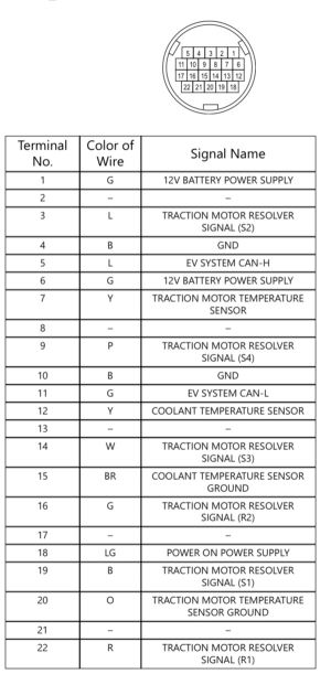
[[File:Leaf PDM Connections.png|thumb|1120x1120px|Leaf PDM connector pinout and physical values. This seems to apply to 2013-2017 Leaf. Check what you have before blindly making any connections.]] | |||
[[File:PDM PINOUT.png|thumb|737x737px]] | |||
[[File:Leafbattery36.png|thumb|638x638px]] | |||
[[File:Nissan-leaf-gen3-inverter-connector.jpg|alt=Gen3 Nissan leaf inverter pinout|thumb|Gen3 Nissan leaf inverter pinout]] | |||
[[Chademo with Zombieverter|Chademo to Zombiverter:]] | |||
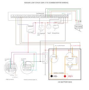
[[File:Zombie-leaf-wiring-gen3.jpg|alt=Nissan Leaf gen 3 to Zombie wiring diagram|thumb|Nissan Leaf gen 3 to Zombie wiring diagram]] | |||
Details can be found on a [[Chademo with Zombieverter|dedicated page.]]<br /> | |||
chademo connector: | |||
HV contactor coil + pin 2 to GP 12v input | |||
HV contactor coil - pin 10 | |||
pin 1 to ground | |||
CAN H pin 8 to CAN EXT 3 H | |||
CAN L pin 9 to CAN EXT 3 L | |||
pin 4 to GP out | |||
Latest revision as of 19:07, 2 October 2025
*this page is a work in progress and may not be fully accurate or up to date.
Setting up a leaf stack with the zombiverter VCU
The full leaf stack ( motor/inverter, pdm (charger, dcdc, hvjb)) can be controlled with the zombieverter VCU.
All you need is 12v+, enable, and CANbus. Note: You still need the OEM connection between the Inverter and Motor Temperature sensors and Resolver for things to function.
As of software release V2.20A, the IVT shunt used for UDC data is no longer required for precharge.
The leaf Inverter itself can supply UDC data for precharge (set the Shunt Type = 0)
the PDM is not needed for UDC data.
The leaf motor and inverter do not require the PDM to run with the zombieverter, or for UDC measurements.
Wiring
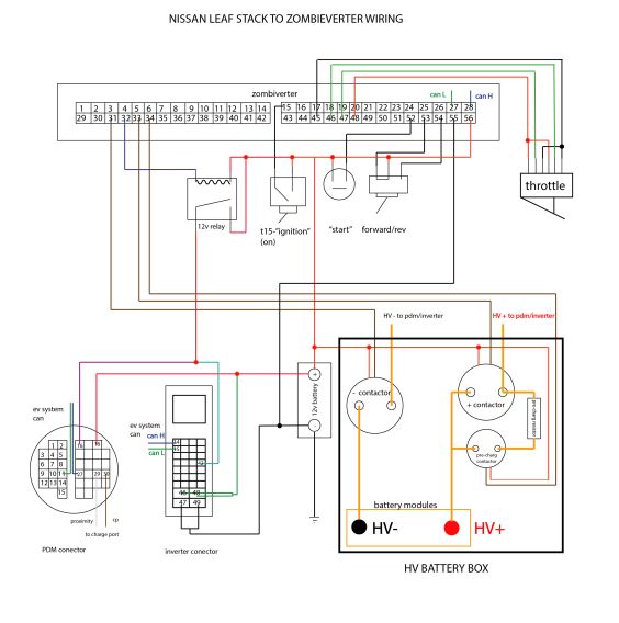
Wiring the zombiverter to the leaf harness
Pinout
| Description | Zombieverter Pin | PDM pin | inverter pin | inverter gen3 pin | battery pin | |
|---|---|---|---|---|---|---|
| +12V | Permanent 12v+ | 56 | 18 | 46, 48 | 1, 6 | 5, 11, 14, 17 |
| Gnd | permanent 12v - | 55 | pdm case | 47, 49 | 4, 10 | 6, 7, 8 |
| Fwd signal | Forward | 54 | ||||
| Rev signal | Reverse | 53 | ||||
| momentary 12V | Start signal | 52 | ||||
| Brake signal | Brake Input | 49 | ||||
| +5V | Throttle | 48 | ||||
| Throttle signal 1 | Throttle signal 1 | 47 | ||||
| Throttle signal 2 | Throttle signal 2 | 46 | ||||
| Throttle Gnd | Throttle Gnd | 45 | ||||
| Precharge Contactor LS Switch | Negative lead from precharge contactor | 34 | 10 | |||
| Main Contactor LS Switch | Negative lead from main contactor | 33 | 16 | |||
| enable relay | switches enable relay | 32 | 16 | 42 | 18 | 31 |
| Neg Contactor LS Switch | Negative lead from negative contactor | 31 | 13 | |||
| CANEXTH | Can 1 High | 28 | 27 | 14 | 5 | 1 |
| CANEXTL | Can 1 Low | 27 | 11 | 15 | 11 | 2 |
| T15 | Ignition 12V in | 15 | 4 | |||
| proximity pilot | pp for charge port | 29 | ||||
| control pilot | cp for charge port | 30 | ||||
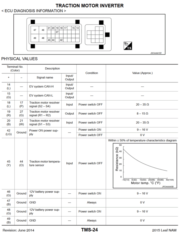
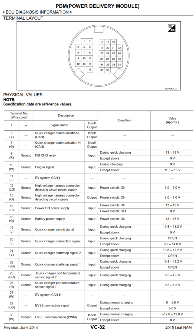
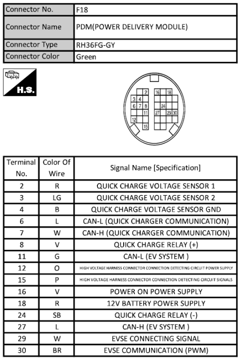
Details can be found on a dedicated page.
chademo connector:
HV contactor coil + pin 2 to GP 12v input
HV contactor coil - pin 10
pin 1 to ground
CAN H pin 8 to CAN EXT 3 H
CAN L pin 9 to CAN EXT 3 L
pin 4 to GP out