Leaf stack with zombiverter: Difference between revisions
Jump to navigation
Jump to search
| Line 22: | Line 22: | ||
CAN L (ev system) pin 11 to CAN EXT 2 L | CAN L (ev system) pin 11 to CAN EXT 2 L | ||
EVSE CONNECTING SIGNAL pin 29 | |||
EVSE COMMUNICATION (PWM) pin 30[[File:ZombieVerter VCU V1 cable side pinout2.jpg|thumb|zombiverter pinout|left|602x602px]] | |||
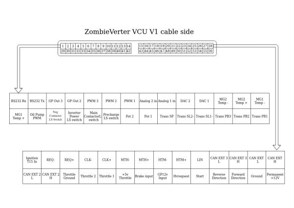
[[File:ZombieVerter VCU V1 cable side pinout2.jpg|thumb|zombiverter pinout|left|602x602px]] | |||
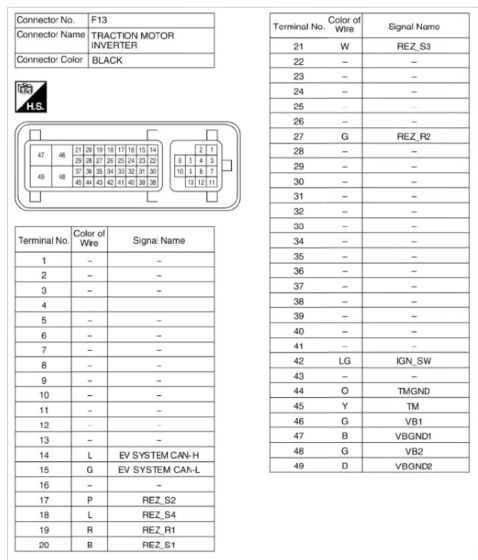
[[File:Leaf inverter pinout.jpg|thumb|leaf inverter connector pinout|560x560px]] | [[File:Leaf inverter pinout.jpg|thumb|leaf inverter connector pinout|560x560px]] | ||
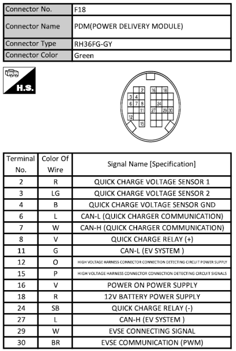
[[File:PDM PINOUT.png|thumb|pinout of the pdm|716x716px]] | [[File:PDM PINOUT.png|thumb|pinout of the pdm|716x716px]] | ||
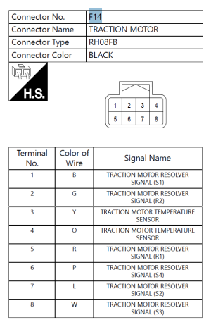
[[File:Leaf resolver pinout.png|thumb|em57 resolver pinout]] | [[File:Leaf resolver pinout.png|thumb|em57 resolver pinout]] | ||
Revision as of 16:27, 24 October 2023
setting up a leaf stack with the zombiverter VCU
the full leaf stack ( motor/inverter, pdm (charger, dcdc, hvjb)) can be controlled with the zombieverter VCU
all you need is 12v and CANbus
wiring
wiring the zombiverter to the leaf harness
the motor/inverter and PDM each use there own canbus
inverter to zombie wiring: EV SYSTEM CAN-H (pin14) to CAN EXT H (pin 28)
EV SYSTEM CAN-L (pin15) to CAN EXT L (pin 27)
PDM to zombie wiring:
CAN H (ev system) pin 27 to CAN EXT 2 H
CAN L (ev system) pin 11 to CAN EXT 2 L
EVSE CONNECTING SIGNAL pin 29
EVSE COMMUNICATION (PWM) pin 30


