Toyota Prius Gen2 Board
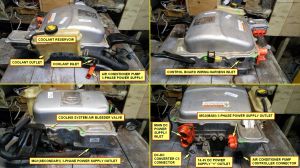

The Toyota Prius is a hybrid vehicle. Their inverters are suitable and attractive for DIY EVs because of:
- Large part availability, Prii have been made in large numbers for 20 years and spares are inexpensive.
- High affordability. Prius inverters are available for around $150 from scrapyards everywhere.
- Durability. Toyota engineers appear to have made the inverters foolproof, many inputs and outputs gracefully handle fault conditions.
- Respectable performance. Rated for 50kW output, but tested to handle 600v, and 350+A for MG2 inverter, 250+A for MG1 inverter, 360kW total (480hp)
- Ease of re-purposing. Emulating the original ECU seems reasonably feasible.
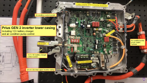
The Gen2 Prius (2004-2009 model years) has a variety of useful components inside the inverter package:
- 2 high power inverters, for the 2 motors MG1 (starter) capable of handling 250 amps, and MG2 (drive motor) capable of handling 350 amps.
- A DC-DC converter to provide 12v and up to 100amps power supply to the automotive systems and accessories.
- A tertiary power inverter to run the A/C, CAN controlled via the "BEAN" (????) network
- A boost module to boost the 200v battery pack up to 500v, which looks to be able to function as a battery charger (wish list for future development)
- See this video for a thorough disassembly and explanation of the Gen2 Inverter (Timestamp 1:15:30): https://www.youtube.com/watch?v=Y7Vm-C4MsW8&t=4531
32-pin Prius Inverter Pin mapping
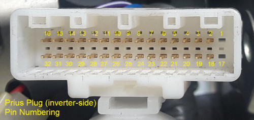
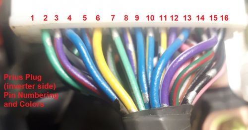
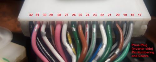
| Pin # | Designation | Description | Wire Color
(Inverter Side) (See pictures to the right) |
Wire Color
(Harness Side) |
|---|---|---|---|---|
| 1 | vacant | |||
| 2 | GIVA | MG1 Phase Current V | LightGreen | White |
| 3 | GIVB | MG1 Phase Current V | Purple-Red | Black |
| 4 | GUU | MG1 PWM U - Speed Signal Wave | Blue | Black |
| 5 | GVU | MG1 PWM V - Speed Signal Wave | Blue-Red | Green |
| 6 | GWU | MG1 PWM W - Speed Signal Wave | Yellow | Yellow |
| 7 | MIVA | MG2 Phase Current V | LIghtGreen-Black | Green |
| 8 | MIVB | MG2 Phase Current V | Purple-Yellow | White |
| 9 | MUU | MG2 PWM U - Speed Signal Wave | Blue-Black | Black |
| 10 | MVU | MG2 PWM V - Speed SIgnal Wave | Blue-Yellow | White |
| 11 | MWU | MG2 PWM W - Speed Signal Wave | Yellow-Black | Red |
| 12 | VH | Inverter Capacitor Voltage | Purple | Yellow |
| 13 | CPWM | Boost converter PWM switch signal | Blue | Black |
| 14 | CT | Boost converter temperature sensor | Green-Red | Red |
| 15 | VL | Boost converter input voltage | Purple-White | Yellow |
| 16 | GINV | Inverter Ground | Black-White | Yellow |
| 17 | vacant | |||
| 18 | GIWA | MG1 Phase Current W | Grey | Red |
| 19 | GIWB | MG1 Phase Current W | Grey-Black | Green |
| 20 | GSDN | MG1 Shutdown | Brown-Black | Red |
| 21 | GIVT | MG1 Inverter Temperature | Green-Black | White |
| 22 | GFIV | MG1 Inverter Fail | White-Grey | Grey |
| 23 | MIWA | MG2 Phase Current W | Grey-Green | Red |
| 24 | MIWB | MG2 Phase Current W | Grey-Red | Black |
| 25 | MSDN | MG2 Shutdown | Brown | Green |
| 26 | MIVT | MG2 Inverter Temperature | Green | Light Blue |
| 27 | MFIV | MG2 Inverter Fail | White | Green |
| 28 | OVH | Overvoltage | Pink | Brown |
| 29 | CSDN | Boost converter shutdown signal | Brown-White | White |
| 30 | FCV | Boost converter fail signal | White-REd | White |
| 31 | OVL | Boost converter over voltage signal | Pink-Blue | Black |
| 32 | GCNV | Boost converter ground | Black-Red | Green |
DC-DC Converter
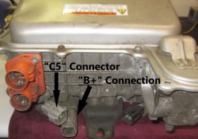
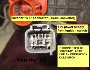
The onboard DC-DC Converter is powered by the high voltage traction battery to supply 12v and up to 100A for low-voltage automotive components and 12 battery maintenance, equivalent to an alternator or generator. Direct control of the converter is simple, only one 12v wire connected to Pin#1 of connector "C5" is necessary to activate it, but a second input can be added at Pin#4, to enhance control.
The 6-pin "C5" connector terminal positions and harness-side colors:
| Pin # | Designation | Description | Wire Color |
|---|---|---|---|
| 1 | IGCT | 12v+ | Blue |
| 2 | ID1 | Not Needed | Purple |
| 3 | S | B+ (opt) | White |
| 4 | NODD | 0-5v+ | Ppl/Gld |
| 5 | VLO | Not Needed | Blue |
| 6 | Vacant |
The case of the inverter must be vehicle ground (12v battery negative terminal), just as an alternator or generator would be.
With the HV bus energized and switched 12v applied to Pin#1 of "C5", the DC-DC will produce 13.2-15.2 Vdc on the large C6 single-conductor connector nearby, which is equivalent to a 12v alternator/generator positive terminal. Depending on voltage applied to pin 4 (if used), output can be tailored; when grounded, it will act as a "KILL" input and DC-DC output will drop to zero. No base load is required to produce voltage.
Note: The output at C6 (large grey connector) is not internally fused and not disabled unless power to Pin#1 of C5 is off, or Pin#4 is grounded, but the DC-DC converter can only produce output when the HV bus is energized.
Note on Limitations - The DC-DC system is not designed to charge up a low 12v battery and certainly not one that's completely dead, doing so can damage the inverter/converter. Pin#1 can be tied directly to the same ignition switch signal as the control board receives as this circuit draws only about 6.3mA.
Inverter Cooling
Inverter coolant enters at the front and exits the rear of the inverter housing from the o-ring port connected to the Hybrid Synergy Drive (HSD) cooling system reservoir.
Through Hole Control Board

The Toyota Prius Gen2 Board is an open source project to repurpose 2004-2009 Toyota Prius inverters for DIY EV use. It consists of a circuit board and programming that replaces the original logic board, connected to the inverter and allows independent control of it without communicating with a Prius ECU.
Note that there is also a Toyota Prius Gen3 Board for the 2010-2015 model years.
As designed by Damien Maguire, the open source hardware for the control board can be purchased as blank, unpopulated boards on his website: Prius Gen2 Logic Board on EVBMW's Webshop
How To Use
The Prius Gen2 Board is suitable to control any (please add: motor types here) motors.
Note: There is a mistake in the printing on the v1 circuit board. The parts labelled T1, T2, and T3 - which are the small black transistors in the upper right of the board - are all drawn backwards to how they need to be inserted. These parts should be installed with the flat side of the component facing the opposite direction as the printing shows. The flat side should be to the right.
Schematics, Bill of Materials, and other documentation are available on Damien's Project Github (note: flesh out bill of materials here, or post changes to Damien to update his documentation directly?)
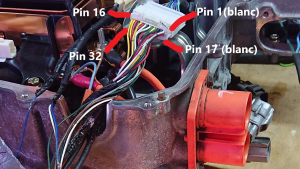
The control board utilizes the Blue Pill (link?) micro controller, and takes advantage of the OpenInverter.org software (link?) for control. It is also connected from the outside via the main (32 pin white) OEM connector - try to retrieve this connector and part of wiring loom when sourcing your inverter. Picture of connector further down in wiki.
The control board design incorporates the use of the existing inverter Current Sensors - if FOC option is to be used (Gen 2 Transaxle MG2), bandwidth should be a multiple of control loop frequency which is 8.8kHz. (link to how to modify original setup?)
Functionality of the existing resolver is integrated as well.
Assembly notes? Blue Pill programming notes or just links to Blue Pill section?
Try to get all the wiring harness bits that plug into the inverter when you purchase it. Else, the 32-pin connector inside the inverter part number is: 1318747-1, and the pins to wire it are: 1123343-1
Terminal Block Connection list (rough, in-progress):
Wire Connections
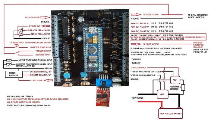
Control Board Pin mapping:
| Pin # | Designation | Description |
|---|---|---|
| TB1-1 | 12v-in | Primary 12v supply from ignition on |
| TB1-2 | GND | Primary ground connection to 12v negative. All grounds are common |
| TB1-3 | 5v VCC | 5V supply from board for use with throttle pot or hall pedal |
| TB1-4 | Throttle In | 0-5v variable voltage input from throttle pedal or pot |
| TB1-5 | Regen In | 0-5v variable voltage input. Can be used as second throttle channel or control regen from a brake pressure sensor |
| TB1-6 | GND | |
| TB1-7 | Brake In | 12v digital input from brake light switch. |
| TB1-8 | Start In | 12v digital input from "Start" position on a traditional ignition switch. Momentary action push button can be used. |
| TB1-9 | For In | 12v digital input commands motor to run in forward direction |
| TB1-10 | Rev In | 12v digital input commands motor to run in reverse direction |
| TB3-1 | +12v VCC | 12v output to inverter IGCT terminal (Not on the 32-pin connector, the red wire on the 2-pin connector next to it). |
| TB3-2 | GND | Common ground, but used to connect to inverter GND terminal (Not on the 32-pin connector, the black wire on 2-pin connector next to it). |
| TB3-3 | Phase U |
Phase U output. Connect to Inverter MUU terminal for MG2 inverter drive or GUU for MG1 inverter drive |
| TB3-4 | Phase Y | Phase V output. Connect to Inverter MVU terminal for MG2 inverter drive or GVU for MG1 inverter drive |
| TB3-5 | Phase W | Phase W output. Connect to Inverter MWU terminal for MG2 inverter drive or GWU for MG1 inverter drive |
| TB3-6 | Current U | Phase currents from inverter. Requires external divider circuit. Not required to run motor or inverter. |
| TB3-7 | Current Y | Phase currents from inverter. Requires external divider circuit. Not required to run motor or inverter. |
| TB3-8 | MG2 Enable | Connect to Inverter MSDN to run MG2 inverter or GSDN to run MG1 inverter |
| TB3-9 | MG2 Fault | Connect to MFIV for MG2 or GFIV for MG1 |
| TB3-10 | DC Bus | Connect to inverter VH to measure DC link voltage |
| TB2-1 | +5V VCC | 5v output to encoder for induction motor |
| TB2-2 | ENCA In | Encoder input A |
| TB2-3 | ENCB In | Encoder input B |
| TB2-4 | GND | Encoder ground |
| TB2-5 | HS Temp | Heatsink temp sensor input |
| TB2-6 | MOT Temp | Motor temp sensor input |
| TB4-1 | GND | Common ground |
| TB4-2 | Main Con | Main HV contactor control low side switch |
| TB4-3 | Precharge | HV precharge contactor control low side switch |
| TB4-4 | +12 V VCC | Spare 12v output |
| TB4-5 | CAN L | Can bus low signal |
| TB4-6 | CAN H | Can bus high signal |
New SMD control board with enclosure and designated pinouts
Please add pictures and description.
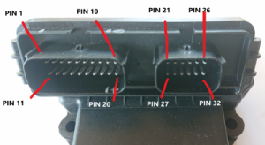
Pin Mapping - Note : Smaller 12-pin socket is the interface to the inverter & 20-pin to the motor
20 - Pin socket
Pin#01 - ENC_B/S3
Pin#02 - S1S4
Pin#03 - ENC_A/S2
Pin#04 - R1
Pin#05 - R2
Pin#06 - 5V
Pin#07 - THROTTLE 1
Pin#08 - THROTTLE 2
Pin#09 - START_IN (12V)
Pin#10 - BRAKE_IN (12V)
Pin#11 - FORWARD_IN (12V) (1, 2 or 3 way switch)
Pin#12 - REVERSE_IN (12V) (1, 2 or 3 way switch)
Pin#13 - Motor Temp -
Pin#14 - Motor Temp +
Pin#15 - DC (HV) Switch Control (Ground signal)
Pin#16 - Pre-ChARGE Control (Ground signal)
Pin#17 - CAN L
Pin#18 - CAN H
Pin#19 - Ground
Pin#20 - 12V "Ignition"
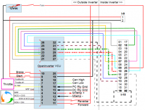
12 - Pin socket ( starts at pin number #21) - Corresponding pin on Main White 32 pin Inverter connector is in brackets.
Pin#21 - GIVA (2)
Pin#22 - MIVA (7)
Pin#23 - GIWA (18)
Pin#24 - MIWA (23)
Pin#25 - VH (12)
Pin#26 - MIVT (26)
Pin#27 - MFIV (27)
Pin#28 - MUU (9)
Pin#29 - MVU (10)
Pin#30 - MWU (11)
Pin#31 - CPWM (13)
Pin#32 - GINV/GCNV (16/32)
Connect MSDN Pin#25 in inverter (not 25 on controller) permanently to 12V to enable the MG2 Inverter (can be tied to same 12v source as "I9")
Connect CPWM to 12V via a 470 Ohm resistor for charge mode.
Connect the 2-pole white power connector ("I9") inside inverter to 12V and Ground to power up inverter electronics.
Make sure to connect Pin #32 and GINV/GCNV to vehicle ground.
Initial Set up
Step 1 : Solder relevant (and included) connector pins to the Adapter Board
Step 2 : Plug in Wifi Adapter and connect ONLY Pin#19 - GROUND and Pin#20 - 12 Volts power supply
Confirm PWR LED lights up along with WIFI LED. Confirm ALIVE LED flashes.
Step 3 : Connect computer/laptop to the wifi network (Example - Inverter 7)
Step 4 : Go to browser toolbar and type in 192.168.4.1 + Enter. (allow pop ups/Trusted site). Confirm Web based Interface appears and list of parameters appear.
If parameters appear, you are now connected to the Adapter board and the Web based Interface - Congratulations - You are now in the Matrix !
Step 5 : Wire up 12 Pin SMD board connector to corresponding 32 Pin Inverter connector, permanent 12 volt supply to Pin #25 (MSDN) of Inverter, and 12V and Ground to 2-pole Inverter connector (next to main 32 pin white connector)
Step 6 : Connect fused 12 volt and Ground to HV Inputs (battery), along with 55 watt light bulb in series (resistor) on the Positive line
Step 7 : Connect fused 12 volt power supply for SMD board , Pin #25, and Inverter 2-pole connector - You are now set up for basic Open Loop motor spinning!
Step 8 : Connect 21 watt light bulbs in Delta connection to the 3 PWM outputs in Inverter (no motor) - https://openinverter.org/forum/download/file.php?id=4273&mode=view
Step 9 : Web Interface Basic parameters set up - to confirm PWM outputs : Full boost with 12v supply, default forward, ampnom @ 70%, and fslipspnt @1 Hz. Select - "Start Inverter in Manual Mode" Confirm flashing lights.
Step 10 : Connect motor phase wires to inverter PWM outputs. Repeat Step 9 and change "fslipspnt" by 1 unit at a time, until motor spins smoothly. (I noticed Light bulb resistor on HV line lights up when no spinning) along with high current values. Once you have the motor spinning, continue to increase the "fslipspnt" value whilst monitoring the current (ampmeter on PWM output wire) You will also notice the light bulb starting to fade untill there is no more light. Optimal motor spinning in Open Loop Mode ! (these values are related to a 12 volt HV supply - re using these parameters is still to be verified at greater supply voltages)
Software
The Control Board runs Open Inverter software. A set of known-good default inverter parameters can be found here: https://openinverter.org/wiki/Configuration_Files#Toyota_Prius_Gen2_Inverter
Do NOT program a deadtime value for the Gen2 inverter. It only uses 1 PWM per phase and the inverter itself generates a low-side and high-side signal WITH deadtime.
Charging
The gen 2 can only charge in buck mode. So maximum charge voltage is limited to the rectified AC input. E.G. From a 230 VAC source the inverter can only charge up to around 320VDC
Relevant Parameters
Charge mode:Buck
Chargecur: 1.5
Chargekp 20
Chargeki: 10
Chargeflt 2 dig
Charge pwmmin: 10 (Change this to get equivalent to min battery voltage.)
udcswbuck: x (HV bus voltage at which point Ground signal is used to control AC and HV battery relays)
Relevant Pins
- CSDN (pin 29 on inverter)
- Shuts down high and low IGBTs when fed 12v, via 470R
- When CSDN is HIGH both IGBTs are OFF.
- CPWM(pin 31 on control board, 13 on inverter)
- Enables charge mode when fed 12v via 470R
- When CPWM is HIGH, the LOW side IGBT is on(shorts out battery), when CPWM is LOW the HIGH side IGBT is on.
- Forward and reverse (11 and 12 on control board)
- Both must be high to enable charging
- DCSW switch(15 in control board)
- Controls DC relay switch.
Physical setup
- 240v AC plugs into two MG1 phases, with a precharge resistor always on.
- Relay controlled by DCSW pin connected to ground side of relay signal wires.
- HV Battery connected with precharge resistor
- Relay controlled from DCSW pin connect to ground side of relay wires.
- CPWM to 12v via 470R resistor. Pulled high to when you want to charge
- CSDN pin to 12v via 470R resistor. Pulled high to when you want to charge
- CSDN pin also tied to DCSW signal pin, which pulls it down when precharge is complete.
Process
- Fwd and reverse signals high, relays open
- CPWM and CSDN pulled high via 470R .
- Connect AC input voltage with precharge
- DCSW will then close relays and pull down CSDN pin to activate charging.
- Activate buck on charger. (By manual web interface or does just having FWD and Reverse high activate this?
- To stop, can change chargecur to 0 or switch off inverter power.