Have you prepared the first board? It needs to R6 to be moved over to R5 (pull-down instead of pull-up)
Have you swapped the diodes on all other boards (i.e. not the first)? Not important for first tests but will generate a 1mA drain.
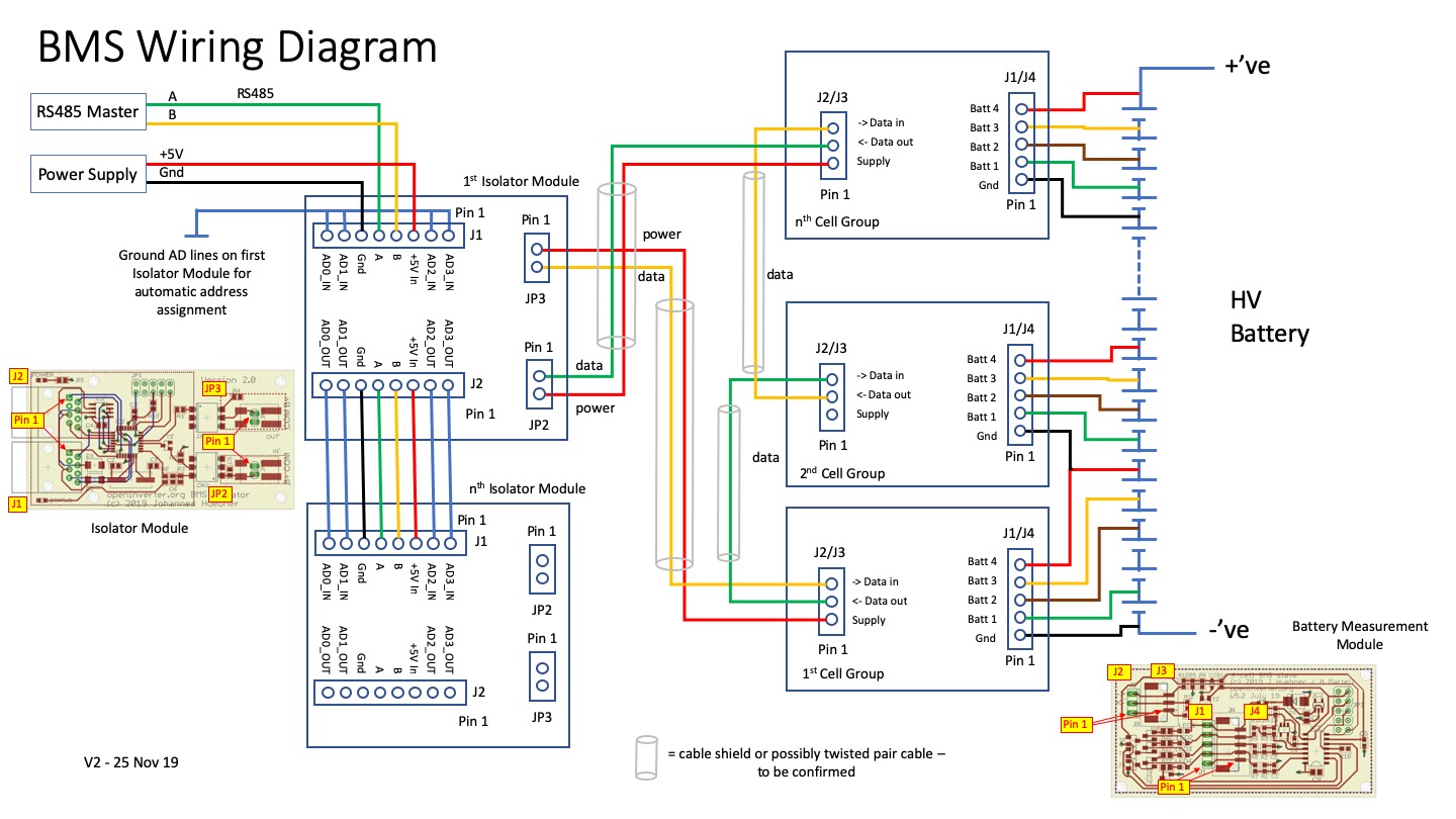
4-channel BMS with daisychain bus
-
johu

- Site Admin
- Posts: 7182
- Joined: Thu Nov 08, 2018 10:52 pm
- Location: Kassel/Germany
- Has thanked: 552 times
- Been thanked: 1918 times
- Contact:
Re: 4-channel BMS with daisychain bus
Support R/D and forum on Patreon: https://patreon.com/openinverter - Subscribe on odysee: https://odysee.com/@openinverter:9
Re: 4-channel BMS with daisychain bus
Thanks. That did the trick. The last email I got from you instructed me to move R12 to R5 instead of R6 
I have swapped all diodes and also added standard JST connectors on all boards.
I have swapped all diodes and also added standard JST connectors on all boards.
Re: 4-channel BMS with daisychain bus
Everything was fine until I changed slaveop to FWUpgrade and now it's on WaitAddr again. Leds on first board are solid as long as it's connected to master unit.
-
johu
- Site Admin
- Posts: 7182
- Joined: Thu Nov 08, 2018 10:52 pm
- Location: Kassel/Germany
- Has thanked: 552 times
- Been thanked: 1918 times
- Contact:
Re: 4-channel BMS with daisychain bus
Oh, remote firmware upgrade gone wrong... just reflash the cell boards and you're back to good.
Support R/D and forum on Patreon: https://patreon.com/openinverter - Subscribe on odysee: https://odysee.com/@openinverter:9
-
Matthew100
- Posts: 7
- Joined: Mon Oct 12, 2020 11:20 am
- Location: Perth, Australia
Re: 4-channel BMS with daisychain bus
Would it be possible in a future revision to be able to simulate a smaller virtual battery?
say for example a hybrid or PHEV you want to primarily use as a PEV. We take a gen2 prius, put 10/20kwh of batteries in it.
The oem system wouldn't use that very well but if artificially suggesting constant higher SOC encouraging the use of more power from the battery until we got down to to a predetermined point and then switched to a small virtual battery that the hybrid system would try and maintain the soc.
-
Jack Bauer

- Posts: 4006
- Joined: Wed Dec 12, 2018 5:24 pm
- Location: Ireland
- Has thanked: 153 times
- Been thanked: 1136 times
- Contact:
Re: 4-channel BMS with daisychain bus
After agonising on how best to connect the bms wires to the slave boards I settled on these solder shrink connectors. Will see how they go the 2 x 100s packs in the E65.
- Attachments
-
-
I'm going to need a hacksaw
-
arber333
- Posts: 3796
- Joined: Mon Dec 24, 2018 1:37 pm
- Location: Slovenia
- Has thanked: 166 times
- Been thanked: 413 times
- Contact:
Re: 4-channel BMS with daisychain bus
You can also buy just the red or white shrink wraps.Jack Bauer wrote: ↑Wed Oct 28, 2020 10:33 am After agonising on how best to connect the bms wires to the slave boards I settled on these solder shrink connectors. Will see how they go the 2 x 100s packs in the E65.
-
bexander

- Posts: 897
- Joined: Tue Jun 16, 2020 6:00 pm
- Location: Gothenburg, Sweden
- Has thanked: 78 times
- Been thanked: 102 times
Re: 4-channel BMS with daisychain bus
What is the status of the next iteration?johu wrote: ↑Thu Aug 06, 2020 5:11 pm I decided to push things forward by publishing some stuff. So:
The Isolator/Master will see one more iteration. Some component values will be changed and it will get the ability to turn itself off. So see for yourself if you're fine with the current version.
- Get your cell modules made at JLCPCB from these files: https://github.com/jsphuebner/bms-hardw ... ng%20Files
- Get the master module made from these files (read below!): https://github.com/jsphuebner/bms-hardw ... ng%20Files
- Get the software here: https://github.com/jsphuebner/bms-software
JLCPCB does not fit any of the connectors so you need to find them somewhere else and solder them yourself.
As always, use the forum. Don't dare privately messaging me if you run into issues but do please post here (or in a dedicated build thread)
The posted binary version of the master firmware is preliminary but good enough for testing.
Is ordering directly from JLCPCB the only way to get the boards? No other source available?
I will, most likely, need a new bms for my new batterypack and this is a good option.
-
Jack Bauer
- Posts: 4006
- Joined: Wed Dec 12, 2018 5:24 pm
- Location: Ireland
- Has thanked: 153 times
- Been thanked: 1136 times
- Contact:
Re: 4-channel BMS with daisychain bus
So I have a string of 23 V5.2 boards running in my E65 front battery just fine. Calibrated and programmed two new V5.3 boards to finish out the 100s pack. When added these two slave boards do not address and also none of the others address. Jumper fitted between pins 4 and 2 on the icsp header. Any help much appreciated:)
I'm going to need a hacksaw
-
johu
- Site Admin
- Posts: 7182
- Joined: Thu Nov 08, 2018 10:52 pm
- Location: Kassel/Germany
- Has thanked: 552 times
- Been thanked: 1918 times
- Contact:
Re: 4-channel BMS with daisychain bus
Whats the value of R6 and C5?
Support R/D and forum on Patreon: https://patreon.com/openinverter - Subscribe on odysee: https://odysee.com/@openinverter:9
-
Jack Bauer
- Posts: 4006
- Joined: Wed Dec 12, 2018 5:24 pm
- Location: Ireland
- Has thanked: 153 times
- Been thanked: 1136 times
- Contact:
-
Jack Bauer
- Posts: 4006
- Joined: Wed Dec 12, 2018 5:24 pm
- Location: Ireland
- Has thanked: 153 times
- Been thanked: 1136 times
- Contact:
Re: 4-channel BMS with daisychain bus
Thanks to Johannes's help I now have calibrated and programmed my first boards and now have 100 cell monitoring up and running on the E65 front pack.
I'm going to need a hacksaw
-
johu
- Site Admin
- Posts: 7182
- Joined: Thu Nov 08, 2018 10:52 pm
- Location: Kassel/Germany
- Has thanked: 552 times
- Been thanked: 1918 times
- Contact:
Re: 4-channel BMS with daisychain bus
Looking forward to a semi-exciting video to dislike 
Support R/D and forum on Patreon: https://patreon.com/openinverter - Subscribe on odysee: https://odysee.com/@openinverter:9
-
ChazFisher
- Posts: 53
- Joined: Wed Jul 03, 2019 1:32 am
- Location: Central Virginia, USA
- Has thanked: 2 times
Re: 4-channel BMS with daisychain bus
I placed my JLCPCB order today. Plan is to start learning how the BMS works with a simple stack of 18650 cells, before committing to the battery pack for my e-motorcycle. Now to go back and read this thread in detail - first order of business is to learn how to calibrate the slaves.johu wrote: ↑Thu Aug 06, 2020 5:11 pm I decided to push things forward by publishing some stuff. So:
The Isolator/Master will see one more iteration. Some component values will be changed and it will get the ability to turn itself off. So see for yourself if you're fine with the current version.
- Get your cell modules made at JLCPCB from these files: https://github.com/jsphuebner/bms-hardw ... ng%20Files
- Get the master module made from these files (read below!): https://github.com/jsphuebner/bms-hardw ... ng%20Files
- Get the software here: https://github.com/jsphuebner/bms-software
JLCPCB does not fit any of the connectors so you need to find them somewhere else and solder them yourself.
As always, use the forum. Don't dare privately messaging me if you run into issues but do please post here (or in a dedicated build thread)
The posted binary version of the master firmware is preliminary but good enough for testing.
Chaz Fisher
Slowly creeping up on that e-motorcycle.
Slowly creeping up on that e-motorcycle.
-
arturk

- Posts: 148
- Joined: Wed Oct 02, 2019 3:58 am
- Location: United States, MD
- Has thanked: 7 times
- Been thanked: 4 times
Re: 4-channel BMS with daisychain bus
I will be looking into it very soon as well since I am going to use this BMS in my conversion.ChazFisher wrote: ↑Wed Nov 25, 2020 9:10 pm ...first order of business is to learn how to calibrate the slaves...
While I am waiting for "cell modules boards" I started working on "master/isolator" (CAN v2).
Q: Is WiFi interface software available for download? The only one I see on GitHub is for Inverter.
1998 Jaguar XJR, GS450h drivetrain, 48kWh/96s BMW battery
-
johu
- Site Admin
- Posts: 7182
- Joined: Thu Nov 08, 2018 10:52 pm
- Location: Kassel/Germany
- Has thanked: 552 times
- Been thanked: 1918 times
- Contact:
Re: 4-channel BMS with daisychain bus
The wifi software is universal - thanks to a defined interface
I will at some BMS specific dash board with voltage bar graphs and such
I will at some BMS specific dash board with voltage bar graphs and such
Support R/D and forum on Patreon: https://patreon.com/openinverter - Subscribe on odysee: https://odysee.com/@openinverter:9
-
arturk
- Posts: 148
- Joined: Wed Oct 02, 2019 3:58 am
- Location: United States, MD
- Has thanked: 7 times
- Been thanked: 4 times
Re: 4-channel BMS with daisychain bus
Thank you for clarification Johannes.
I suspected it and loaded latest "esp8266-web-interface" hoping to see some BMS functionality based on earlier post:
I understand now it is still under development.
1998 Jaguar XJR, GS450h drivetrain, 48kWh/96s BMW battery
-
TonyV
- Posts: 87
- Joined: Sat Nov 14, 2020 9:00 pm
- Location: Toronto
- Has thanked: 1 time
- Been thanked: 12 times
- Contact:
Re: 4-channel BMS with daisychain bus
Hi everyone,
kinda of a new guy here,
I have a question about the wiring of the "1st cell group" battery management board.
I'm I missing something here but, shouldn't Batt 2 wire be connected to the cell below it?
I hope I don't sound like an idiot.
kinda of a new guy here,
I have a question about the wiring of the "1st cell group" battery management board.
I'm I missing something here but, shouldn't Batt 2 wire be connected to the cell below it?
I hope I don't sound like an idiot.
I'll figure this out sooner or later
-
johu
- Site Admin
- Posts: 7182
- Joined: Thu Nov 08, 2018 10:52 pm
- Location: Kassel/Germany
- Has thanked: 552 times
- Been thanked: 1918 times
- Contact:
Re: 4-channel BMS with daisychain bus
Not at all, an extra cell slipped in there
The diagram is slightly outdated as isolator and master are no longer split.
Support R/D and forum on Patreon: https://patreon.com/openinverter - Subscribe on odysee: https://odysee.com/@openinverter:9
-
TonyV
- Posts: 87
- Joined: Sat Nov 14, 2020 9:00 pm
- Location: Toronto
- Has thanked: 1 time
- Been thanked: 12 times
- Contact:
Re: 4-channel BMS with daisychain bus
Any time line as to when these are for sale to the masses?
I'll figure this out sooner or later
-
arturk
- Posts: 148
- Joined: Wed Oct 02, 2019 3:58 am
- Location: United States, MD
- Has thanked: 7 times
- Been thanked: 4 times
Re: 4-channel BMS with daisychain bus
After couple of days of hard work programming and calibrating I was finally able to run first, somewhat successful test with CAN Isolator v2 and 2 Cell Modules v5.2 on 12s test battery pack.
It seems to work however I do not see any values from BMS reported in the "Spot Values" section on WiFi interface, all values show '0'
Modules seem to be addressing and communicating, so at this point I would expect to see some real values for Pack Voltage, average
and perhaps individual cells voltages.
I have no prior experience with OpenInerter platform and unified WiFi interface so I could have missed something.
Any tips would be greatly appreciated.
- Attachments
-
-
-
1998 Jaguar XJR, GS450h drivetrain, 48kWh/96s BMW battery

Re: 4-channel BMS with daisychain bus
Did you do the oscillator-calibration correctly? It looks like the lights on the slaves are blinking in different frequencies.
Robin Guldmyr
MR Electronics AB
MR Electronics AB
-
johu
- Site Admin
- Posts: 7182
- Joined: Thu Nov 08, 2018 10:52 pm
- Location: Kassel/Germany
- Has thanked: 552 times
- Been thanked: 1918 times
- Contact:
Re: 4-channel BMS with daisychain bus
It looks like the cell modules receive the "set address" command fine as they stop blinking. But the master does not receive it back. Can you try switching polarity from 2nd module back to master?
EDIT: I have also had trouble with filtering. You can try replacing R14 with 1M or 470k and removing C20 if still not working.
EDIT: I have also had trouble with filtering. You can try replacing R14 with 1M or 470k and removing C20 if still not working.
Support R/D and forum on Patreon: https://patreon.com/openinverter - Subscribe on odysee: https://odysee.com/@openinverter:9
-
arturk
- Posts: 148
- Joined: Wed Oct 02, 2019 3:58 am
- Location: United States, MD
- Has thanked: 7 times
- Been thanked: 4 times
Re: 4-channel BMS with daisychain bus
Success!
It was polarity as, silly mistake of me not checking it.
I am getting voltages of my 8 cells reported as well as averages and temps
Also, checked signal quality on the return channel (U6.4) and looks pretty clean, at least in this simple test setup. I will keep an eye on it as I expand system.
Next step is to update my calibration rig to get ADC calibration more accurate (just used series of resistors for this first test ) . I am good on clock/oscillator.
It was polarity as, silly mistake of me not checking it.
I am getting voltages of my 8 cells reported as well as averages and temps
Also, checked signal quality on the return channel (U6.4) and looks pretty clean, at least in this simple test setup. I will keep an eye on it as I expand system.
Next step is to update my calibration rig to get ADC calibration more accurate (just used series of resistors for this first test
Very important point indeed. I made sure oscillators were calibrated as difference prior calibration was really huge. This may be hard judge from the video since I plugged in batteries by hand individually. Using Arduino Micro with timer programmed to generate 2kHz signal. It is pretty accurate.
1998 Jaguar XJR, GS450h drivetrain, 48kWh/96s BMW battery
-
arturk
- Posts: 148
- Joined: Wed Oct 02, 2019 3:58 am
- Location: United States, MD
- Has thanked: 7 times
- Been thanked: 4 times
Re: 4-channel BMS with daisychain bus
Johannes, do you see any possibility of adding external temperature sensor support to cell module?
I know we do not have any more "free" pins available but was about PA3.
It seems like it was intended as 3V reference but is it really being used that way?
I know we do not have any more "free" pins available but was about PA3.
It seems like it was intended as 3V reference but is it really being used that way?
1998 Jaguar XJR, GS450h drivetrain, 48kWh/96s BMW battery