Help! Prius gen3 inverter using ABZ encoder

Topics concerning the Toyota and Lexus inverter drop in boards
m.art.y
Posts: 658
Joined: Sat Jun 06, 2020 6:54 pm
Location: UK/EU
Has thanked: 35 times
Been thanked: 33 times

Help! Prius gen3 inverter using ABZ encoder

Post by m.art.y »

Hello, I will try to start this thread both hoping for help and guidance and also to serve as documentation and testing ground in trying to use openinverter software in a gen3 Prius inverter using ABZ encoder. This encoder comes installed in a permanent magnet synchronous 8 pole motor made by Leroy Somer.
Image
Image
Image

I got the motor to spin in open loop mode using gen3 inverter. I would like to proceed and try to test if it is possible to use the encoder to run the motor with FOC firmware. I don't really know how to proceed, but I would appreciate the help and guidance and I am ready to follow instructions. Johannes has already mentioned that ABZ encoders are untested to say the least. But is there any chance that this might work?

Other thoughts I am having - is it possible to use some sort of conversion board to convert ABZ to more suitable signal for open inverter?
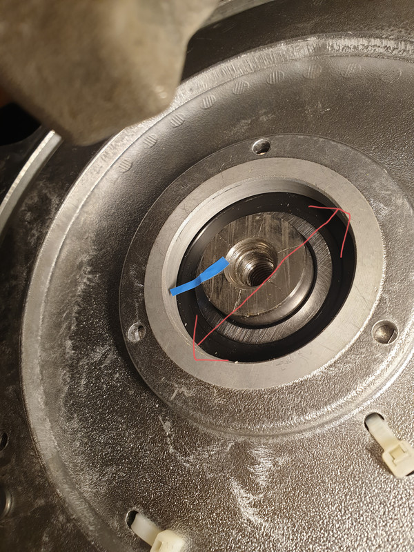
If all the above fails I will try to use RLS encoder as kindly suggested by arber333. However due to precise mounting tolerances I am a touch frightened if I will be able to achieve those.

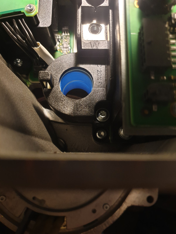
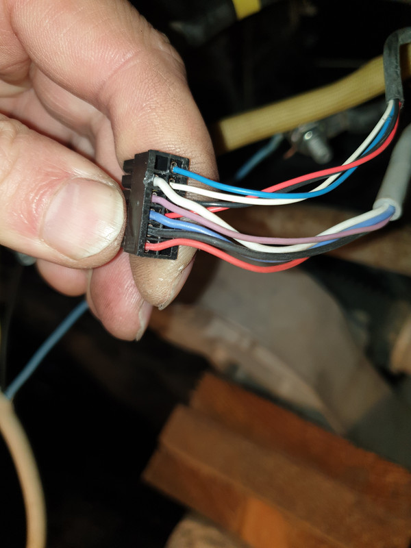
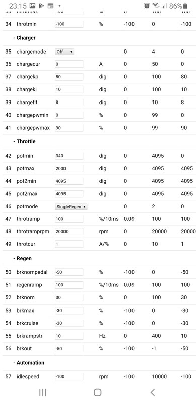
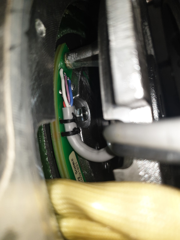
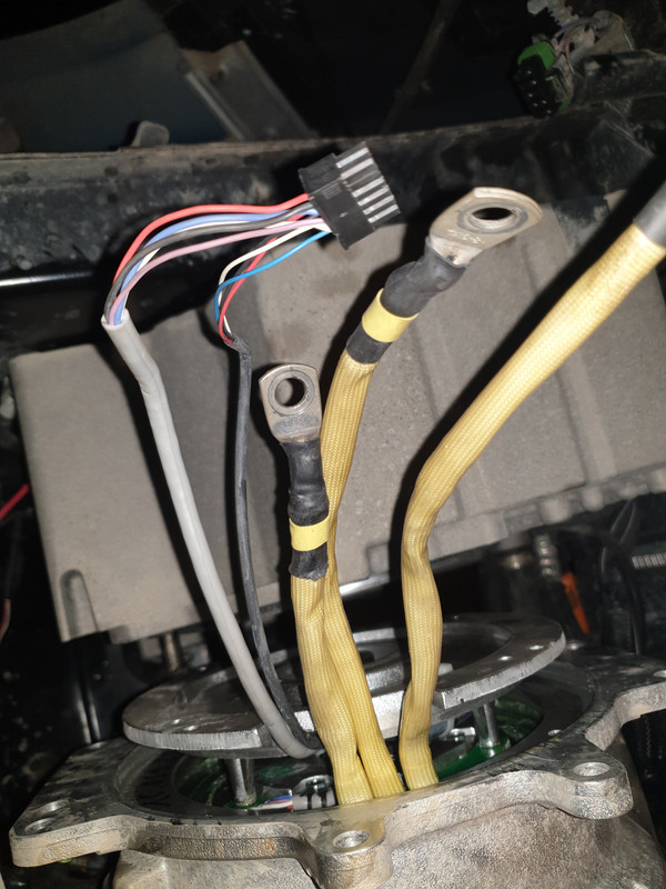
First uncertainty regarding the use of ABZ encoder that I have - openinverter firmware allows to choose ABZ as encoder type but there only seems to be 2 encoder inputs. Let's say I find which wires are A, B and Z, which ones I actually need to wire into gen 3 Prius inverter?
arber333
Posts: 3567
Joined: Mon Dec 24, 2018 1:37 pm
Location: Slovenia
Has thanked: 134 times
Been thanked: 336 times
Contact:

Re: Help! Prius gen3 inverter using ABZ encoder

Post by arber333 »

First separate the wires for the temperature probe. There are two wires that go towards the back of motor winding. Usually that is KTY84 motor sensor. I see you have 4 wires going to the sensors you may have two sensors in the wiring... can you measure their ohm value? White and blue wire against black?

Then there should be 5 wires. Try to figure out the wiring. First find the power supply Vcc and GND. Two wires will be different than the rest. I see you have red and black wires. That should be it then. Red should be Vcc and black GND.
Power it up with 5V. Then find the Z wire. I used one LED from signal wires towards GND. When you turn the shaft by hand the Z channel will blink only once per turn. Blue, pink or white. Mark that wire and there you go.
Two other wires are A and B then. They respond to shaft turning with train of pulses. You cant tell A from B without oscilloscope. But that actually isnt the problem. You need to know the pulse count to use the encoder.
Try to read the text on encoder. Or take a photo. I can see part of the text from your 2nd photo. This will help you find the datasheet which will tell you how many pulses it generates.

Also the openinverter actually has 3 encoder inputs. Its just the PD2 is used as an exciter output by resolver mode. A and B are PA7 and PA6.
Read this: viewtopic.php?f=2&t=15
And see the schematic of your board on github.
arber333
Posts: 3567
Joined: Mon Dec 24, 2018 1:37 pm
Location: Slovenia
Has thanked: 134 times
Been thanked: 336 times
Contact:

Re: Help! Prius gen3 inverter using ABZ encoder

Post by arber333 »

You may have UVW encoder! In that case you wont be able to use it with openinverter. It will be easier to replace it by sin/cos RLS.
See here on page 16 there is a wiring. Do you have such connector?
https://driveka.ru/upload/iblock/0e3/ls ... 2.05eo.pdf
Also another document page 42 and 43.
https://assets.euautomation.com/uploads ... sp4403.pdf

First lets see the number on encoder.
m.art.y
Posts: 658
Joined: Sat Jun 06, 2020 6:54 pm
Location: UK/EU
Has thanked: 35 times
Been thanked: 33 times

Re: Help! Prius gen3 inverter using ABZ encoder

Post by m.art.y »

arber333 wrote: Fri Nov 27, 2020 9:57 pm First lets see the number on encoder.
Which number? That is very interesting, should I try pulling the entire encoder out and see if we can make anything out? The connector is pictured above. It was plugged into the original inverter the motor was used with (OEM vehicle, entire drive train made by ACTIA). All 3 phase leads were wired through a blue ring looking thing in the inverter - hall effect current sensor?

Image

Image
m.art.y
Posts: 658
Joined: Sat Jun 06, 2020 6:54 pm
Location: UK/EU
Has thanked: 35 times
Been thanked: 33 times

Re: Help! Prius gen3 inverter using ABZ encoder

Post by m.art.y »

Image
This is the connector of the encoder. Inside the lead with 5 wires 1 out of 3 signal wires is visually smaller. I was hoping it might be the Z wire.
I have made the led test. I connected 5 v to vcc and ground and i attached led to a ground wire and each of the signal wires and I spun the motor with prius inverter in open loop mode. Good news led was blinking with each of the signal wires. Bad news led was blinking more than once per motor revolution with each signal wire.

EDIT:
I have spun the motor by hand and it moves in exact same steps. I can count the steps and count when each signal wire becomes lit and for how many steps stays lit. At least one of the signal wires becomes lit at a different step than the other 2 signal wires. Each wire produces 4 pulses per one full motor revolution (led lights up 4 times). If that would make any difference I can count everything precisely and produce a graph. All the above is about the 5 wire lead. But what do my findings mean?


Now is it worth trying the other lead with 4 wires?

EDIT: I tried feeding 5v into the red and black wires on the 4 wire lead and connected led to each white and blue wires and none produced any blinking of led.
arber333
Posts: 3567
Joined: Mon Dec 24, 2018 1:37 pm
Location: Slovenia
Has thanked: 134 times
Been thanked: 336 times
Contact:

Re: Help! Prius gen3 inverter using ABZ encoder

Post by arber333 »

m.art.y wrote: Sat Nov 28, 2020 10:54 am I have made the led test. I connected 5 v to vcc and ground and i attached led to a ground wire and each of the signal wires and I spun the motor with prius inverter in open loop mode. Good news led was blinking with each of the signal wires. Bad news led was blinking more than once per motor revolution with each signal wire.

EDIT:
I have spun the motor by hand and it moves in exact same steps. I can count the steps and count when each signal wire becomes lit and for how many steps stays lit. At least one of the signal wires becomes lit at a different step than the other 2 signal wires. Each wire produces 4 pulses per one full motor revolution (led lights up 4 times). If that would make any difference I can count everything precisely and produce a graph. All the above is about the 5 wire lead. But what do my findings mean?
I am deaering my charging system...lots of dirty work...
Well unfortunately it looks like you have UVW commutation encoder. One pulse per magnet moving across the hall sensor. Sadly this type of encoder won't work with openinverter. Lebowski would work. But board wasnt developed for Prius inverter yet.

Rest of wires may be SSI serial interface.

I would recommend to go with RLS.
Yes your option with bolt would work.
Be aware though you need to use nonferrous bolt. Best use aluminum. Also try it first without magnet so you can devise a sort of locking mechanism. Maybe a counter nut?

And when you work with RLS plate be sure to make an interface board that will let RLS slide directly into center.
m.art.y
Posts: 658
Joined: Sat Jun 06, 2020 6:54 pm
Location: UK/EU
Has thanked: 35 times
Been thanked: 33 times

Re: Help! Prius gen3 inverter using ABZ encoder

Post by m.art.y »

arber333 wrote: Sat Nov 28, 2020 3:56 pm
Be aware though you need to use nonferrous bolt. Best use aluminum. Also try it first without magnet so you can devise a sort of locking mechanism. Maybe a counter nut?

And when you work with RLS plate be sure to make an interface board that will let RLS slide directly into center.
Thanks, I overlooked that bit about it being nonferrous metal. I looked and there seems to be no aluminium bolts easily available. Will have to have it made on a lathe. By interface board you mean some sort of adapter to accept the RLS round plate? Also how would I wire it to the prius inverter when I have it made?

Also very important question: I plan to run the prius inverter at the back of the car either in the boot or in a battery box under the car. Would there be no problem for the signal from RLS to travel that far using shielded ethernet cable for example? Also is this a good idea in general to run 3 phase wires from the battery box or the boot of the car? There is no space in the engine bay.

Thanks again.
arber333
Posts: 3567
Joined: Mon Dec 24, 2018 1:37 pm
Location: Slovenia
Has thanked: 134 times
Been thanked: 336 times
Contact:

Re: Help! Prius gen3 inverter using ABZ encoder

Post by arber333 »

m.art.y wrote: Sat Nov 28, 2020 6:21 pm Thanks, I overlooked that bit about it being nonferrous metal. I looked and there seems to be no aluminium bolts easily available. Will have to have it made on a lathe. By interface board you mean some sort of adapter to accept the RLS round plate? Also how would I wire it to the prius inverter when I have it made? Thanks again.
Well you need to make 44mm recess in your mount center. Make it like 2mm deep with central hole so that when you mount your bolt in center of shaft it will almost touch the underside of RLS metal pad.
You need to get pad in center with 0.1mm accuracy, but magnet distance is good up to 1mm from the pad underside.

I suggest a 4 wire LiYCY cable which is shielded cable. You solder the wires directly onto the RLS encoder circuit and put a blob of nail polish or paint on it. You find a place to connect shield inside motor case and use a zip tie to fix the cable in place inside. Then you find a gland through which you will fit the cable out.
You will have to calibrate the sensor with the motor. After mounting the sensor you will supply 5V to the sensor and give 12Vdc to 2 of the motor phases to align first magnet to stator. Then you short two pads on the encoder PCB for a second. Encoder will remember position and that will be your 0° angle,
RLS encoder you need to select according to the pole count! This is really important so let them know your motor parameters in a comment or message.
I think your encoder will be P/N RMF44AC01SA10 and magnet you will select RMM44A3A00. See their online store.
https://www.rls.si/eng/rmf44-rotary-mag ... RMM44A3A00

Also this is the recent datasheet
https://www.rls.si/eng/fileuploader/dow ... _sheet.pdf

Be advised this is a single pole signal. So in your parameters you will set 4pole pairs for motor and 1 pole pair for sin/cos not resolver. This is because RLS encoder has its own excitation.
User avatar
mdrobnak
Posts: 692
Joined: Thu Mar 05, 2020 5:08 pm
Location: Colorado, United States
Has thanked: 1 time
Been thanked: 5 times

Re: Help! Prius gen3 inverter using ABZ encoder

Post by mdrobnak »

So, before we go down the modifying path, is there:
A) A hardware method to convert this to something more useful to the OI board?
B) A software method to understand this signal in the OI software?

I'd say it's definitely desirable to not mess with things that have tight tolerances unless absolutely necessary.

(yes there will be a delay if doing a conversion, but that should be effectively offset via the syncofs setting I would think).

-Matt
arber333
Posts: 3567
Joined: Mon Dec 24, 2018 1:37 pm
Location: Slovenia
Has thanked: 134 times
Been thanked: 336 times
Contact:

Re: Help! Prius gen3 inverter using ABZ encoder

Post by arber333 »

mdrobnak wrote: Sat Nov 28, 2020 7:48 pm B) A software method to understand this signal in the OI software?
Johannes, is there a way to modify software to use current ABZ pins to sense UVW commutation pulses? This is the common 6 step commutation all china BLDC scooters use. https://www.digikey.com/en/articles/wha ... bldc-motor

I think the RLS encoder that i gave you some time ago has option of output UVW. Just saying... 8-).
m.art.y
Posts: 658
Joined: Sat Jun 06, 2020 6:54 pm
Location: UK/EU
Has thanked: 35 times
Been thanked: 33 times

Re: Help! Prius gen3 inverter using ABZ encoder

Post by m.art.y »

mdrobnak wrote: Sat Nov 28, 2020 7:48 pm So, before we go down the modifying path, is there:
A) A hardware method to convert this to something more useful to the OI board?
B) A software method to understand this signal in the OI software?

I'd say it's definitely desirable to not mess with things that have tight tolerances unless absolutely necessary.

(yes there will be a delay if doing a conversion, but that should be effectively offset via the syncofs setting I would think).

-Matt
I absolutely agree. I had thought about a signal conversion option however I was not able to find anything on google and I do not know if such a solution even exists. If anybody knows something please let me know. I also have not got time or ability to design such a solution from scratch.

So I am willing to go for a known working solution which involves some machining work. I did think about it and I think it should be possible.
m.art.y
Posts: 658
Joined: Sat Jun 06, 2020 6:54 pm
Location: UK/EU
Has thanked: 35 times
Been thanked: 33 times

Re: Help! Prius gen3 inverter using ABZ encoder

Post by m.art.y »

arber333 wrote: Sat Nov 28, 2020 6:56 pm
Well you need to make 44mm recess in your mount center. Make it like 2mm deep with central hole so that when you mount your bolt in center of shaft it will almost touch the underside of RLS metal pad.
Image

Unless Johannes is willing to make a software solution this is my plan so far. :) This is where I plan to mount the RLS encoder - on top of the original encoder. The diameter indicated with the arrow is 52.56 mm. I will make an adapter ring with protruding edges to accomodate RLS pcb round plate and it will slide into that space in between the encoder shaft and the encoder mounting plate (in between the red arrow). Then I will make aluminium bolt to screw into the shaft and in the bolt there will be a magnet glued in. If need be I can loctite the bolt into the shaft, hopefully it will stay there. I will flatten two sides on the bolt so it can still be screwed in there with a special tool (as bolt will not have a head). What do you think Arber? 🙂

Also I understand the RLS pcb is already centered within it's round plate? I will only need to center the round plate around the shaft?

Do you think there might be issues with signal if I use 3 meter shielded cable to run it to the boot or battery box under the car where I plan to mount my inverter? Thanks 🙂
arber333
Posts: 3567
Joined: Mon Dec 24, 2018 1:37 pm
Location: Slovenia
Has thanked: 134 times
Been thanked: 336 times
Contact:

Re: Help! Prius gen3 inverter using ABZ encoder

Post by arber333 »

Yes you have the right idea! Maybe you can shim the alu bolt so you get it to correct height without much fuss.

3m cable seems a bit much, cant you use shorter cable?
If you cant go past that be extra carefull to rout the cable far away from DC and phase cables! 50cm should be enough if you use shield.
Also you need to ground both motor and inverter. Make a good connection to car chasiss. Use a 16mm2 cable or more!
m.art.y
Posts: 658
Joined: Sat Jun 06, 2020 6:54 pm
Location: UK/EU
Has thanked: 35 times
Been thanked: 33 times

Re: Help! Prius gen3 inverter using ABZ encoder

Post by m.art.y »

arber333 wrote: Sat Nov 28, 2020 9:59 pm 3m cable seems a bit much, cant you use shorter cable?
If you cant go past that be extra carefull to rout the cable far away from DC and phase cables!
Since I have to run the cable to the middle or the back of the car where I plan to mount my inverter I'm not sure if I can make it shorter. I was planning to run it near where I am planning to run my 3 phase cables from the inverter. I could run it on the other side of the car away from 3 phase cables but then it would be the longer route. Would it be better to use longer cable but away from 3 phase cables?
Thanks for warning about grounding the inverter. I was not aware of that.
arber333
Posts: 3567
Joined: Mon Dec 24, 2018 1:37 pm
Location: Slovenia
Has thanked: 134 times
Been thanked: 336 times
Contact:

Re: Help! Prius gen3 inverter using ABZ encoder

Post by arber333 »

m.art.y wrote: Sat Nov 28, 2020 10:24 pm Thanks for warning about grounding the inverter. I was not aware of that.
That is one of the main requirements in legislation.

Dang! I managed to install the second charger and feed coolant to it. I am a mess now :shock:. But everything works now...
Cant you mount inverter over the motor? Phase cables need to be as close as possible to motor. Long phase cables ring tremendously. Also there are losses in that. You can bring DC power towards inverter wherever you need it, but phase cables... just saying.
m.art.y
Posts: 658
Joined: Sat Jun 06, 2020 6:54 pm
Location: UK/EU
Has thanked: 35 times
Been thanked: 33 times

Re: Help! Prius gen3 inverter using ABZ encoder

Post by m.art.y »

arber333 wrote: Sat Nov 28, 2020 11:37 pm
Cant you mount inverter over the motor? Phase cables need to be as close as possible to motor. Long phase cables ring tremendously. Also there are losses in that. You can bring DC power towards inverter wherever you need it, but phase cables... just saying.
I did not know this either, thanks! It is a very steep learning curve for me, I'm doing things I have never done before, I have to find everything out. Will it help if I use shielded phase cables? They will be around 2 meters long at the moment. There is no space anywhere else to mount the inverter at the moment. In the long run I will try to make the original inverter work with CAN comands when I have more time to work them out. At the moment I need to make it drive.
Isaac96
Posts: 656
Joined: Sat Oct 05, 2019 6:50 pm
Location: Northern California, USA
Been thanked: 2 times
Contact:

Re: Help! Prius gen3 inverter using ABZ encoder

Post by Isaac96 »

Ringing is caused by the inductance of the wires. If I remember correctly, using thicker wires will reduce ringing. Shielding will reduce the electrical noise in other components.
User avatar
johu
Site Admin
Posts: 6735
Joined: Thu Nov 08, 2018 10:52 pm
Location: Kassel/Germany
Has thanked: 379 times
Been thanked: 1560 times
Contact:

Re: Help! Prius gen3 inverter using ABZ encoder

Post by johu »

UVW has quite bad resolution, maybe tolerable for hobby stuff and e-bikes but not high power car motors. Unless you switch over to sensorless at higher speed. Which OI software doesn't implement either.
Lastly the third timer channel needed for this is occupied by some analog input...
To sum it up: I can't really be bothered ;) I've done it before in some other project, it's not hard to do if you're motivated.
Support R/D and forum on Patreon: https://patreon.com/openinverter - Subscribe on odysee: https://odysee.com/@openinverter:9
m.art.y
Posts: 658
Joined: Sat Jun 06, 2020 6:54 pm
Location: UK/EU
Has thanked: 35 times
Been thanked: 33 times

Re: Help! Prius gen3 inverter using ABZ encoder

Post by m.art.y »

arber333 wrote: Sat Nov 28, 2020 11:37 pm Long phase cables ring tremendously. Also there are losses in that. You can bring DC power towards inverter wherever you need it, but phase cables... just saying.
You're right. I did some googling apparently that is an issue with variable speed drives. Can damage the motor and the leads. However I did not find any info on EV's on the matter. They were talking industrial applications and mentioned cable lengths over 7 meters. How long would be too long in a EV?

Ordered RLS encoder. Want to get ready the wiring. What are the minimum inputs that openinverter needs? I plan to make forward, reverse and start on the can commands. Also accelerator on CAN if I can manage. Obviuosly it will need inputs for sin/cos. What else? Can I leave all the others? Is cruise and breaking necessary if I don't plan to use regen for now. Thanks :)
slow67
Posts: 151
Joined: Thu Jan 30, 2020 6:52 pm
Location: Texas
Been thanked: 1 time

Re: Help! Prius gen3 inverter using ABZ encoder

Post by slow67 »

https://youtu.be/TH14ry6TOy8

There is a resolver to UVW, I can’t remember if it does the other way around. Also, it wouldn’t be too difficult to take an arduino/stm32/teensy to take the signal input and convert it to resolver signal. Also could estimate the position between UVW signals based in current motor speed and acceleration.
arber333
Posts: 3567
Joined: Mon Dec 24, 2018 1:37 pm
Location: Slovenia
Has thanked: 134 times
Been thanked: 336 times
Contact:

Re: Help! Prius gen3 inverter using ABZ encoder

Post by arber333 »

slow67 wrote: Mon Nov 30, 2020 2:38 pm https://youtu.be/TH14ry6TOy8

There is a resolver to UVW, I can’t remember if it does the other way around. Also, it wouldn’t be too difficult to take an arduino/stm32/teensy to take the signal input and convert it to resolver signal. Also could estimate the position between UVW signals based in current motor speed and acceleration.
Incidentaly Prius inverter has a chip that is able to convert resolver signal into UVW...
Well as i am ME i much rather go with mechanical solutions.
Still to correctly gauge rotor position you need amplitude rise and UVW are discrete signals. Converting them back would be like taking the chopped wood back in the forest 8-) .
m.art.y
Posts: 658
Joined: Sat Jun 06, 2020 6:54 pm
Location: UK/EU
Has thanked: 35 times
Been thanked: 33 times

Re: Help! Prius gen3 inverter using ABZ encoder

Post by m.art.y »

Image

I've got a throttle pedal that one of the channels gives 0.389 v at rest and 2.064 v fully pressed. The other channel I did not manage to get any reading out when pressing the pedal so far. I'm not sure how to enter the values into firmware. I entered as above and it gives me strange readings when I try to plot the pot value. What have I done wrong?
m.art.y
Posts: 658
Joined: Sat Jun 06, 2020 6:54 pm
Location: UK/EU
Has thanked: 35 times
Been thanked: 33 times

Re: Help! Prius gen3 inverter using ABZ encoder

Post by m.art.y »

arber333 wrote: Sat Nov 28, 2020 6:56 pm RLS encoder you need to select according to the pole count! This is really important so let them know your motor parameters in a comment or message.
I think your encoder will be P/N RMF44AC01SA10 and magnet you will select RMM44A3A00. See their online store.
https://www.rls.si/eng/rmf44-rotary-mag ... RMM44A3A00
Hi Arber. I ordered as the above and made a comment that my motor was 8 pole synchronous motor and I asked them to configure as such. They did not seem to understand what I was asking as I got a reply:
'For commutation (if I understood your question correctly you are seeking 8 pole pair commutation) use WH or UH configuration – for more details please check our web page and configure the most suitable for your demand.'
What shall I do?
arber333
Posts: 3567
Joined: Mon Dec 24, 2018 1:37 pm
Location: Slovenia
Has thanked: 134 times
Been thanked: 336 times
Contact:

Re: Help! Prius gen3 inverter using ABZ encoder

Post by arber333 »

No no. You tell them you need sin/cos resolver signal for inverter. Now you have UVW encoder and it is no good for your application. You have 8 pole motor so that is 4pairs no????
Probably Sergio is trying to think ahead instead of you? Just tell him you need sin/cos output.

BR

Arber
m.art.y
Posts: 658
Joined: Sat Jun 06, 2020 6:54 pm
Location: UK/EU
Has thanked: 35 times
Been thanked: 33 times

Re: Help! Prius gen3 inverter using ABZ encoder

Post by m.art.y »

Ok so the original UVW encoder is responsible for providing the speed of the car to the speedometer. At first I thought it was the wheel sensors that report the speed but I was wrong. Good that I chose to leave the original encoder in place and mount the sin/cos encoder on top of it. That way I can still have the speedometer working.

I got the motor spinning with throttle pedal with the sine firmware. Not very smoothly at the moment. But it spins rather nicely in testing mode. Anybody knows if it is in fact possible to drive the car with synchronous motor in sensorless mode with sine firmware? Which parameters I should try to adjust? Thanks 🙂
Post Reply