Yeah I see what Johannes said and I see AD needs it because of threshold. So this might work even with 10K.
But you need to transfer RLS 0V center to 0 to 3V3 function. For that you need some pullup to anchor one side of encoder to 0.5V instead of -1V. I have one RLS sin/cos at home but i haven't tried it with openinverter yet. You will have to be the first, sorry.
A
Help! Prius gen3 inverter using ABZ encoder
-
m.art.y
- Posts: 715
- Joined: Sat Jun 06, 2020 6:54 pm
- Location: UK/EU
- Has thanked: 38 times
- Been thanked: 37 times
Re: Help! Prius gen3 inverter using ABZ encoder
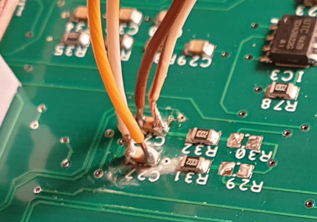
Is that still the plan to put those resistors over C27 and C28 or that is something different? If you could tell me what to wire where I can do it.
I have removed R29 and R30 from the inverter board. Now I get a signal that is roughly from 0 to 360 degrees. However the signal curve does not resemble that of Damiens in the FOC tuning video. I attach a couple screenshots:
I tried to add some manualid across the lightbulb and lightbulb iluminates and I can hear a whine from the motor but no movement. I went up to 20 A manualid across the lightbulb but no movement of motor at all. I had 74V battery connected and settings as per the video. I selected pinswap pwmoutput23 option. Then I decided to remove the lightbulb and add 1A manualid and I noticed wires from the battery getting hot instantly - so inverter was pulling way too much current from the battery. I can run the motor with sine firmware no problem with same wires and they are not even getting warm. Can this be the encoder that is causing this? Wouldn't the motor even try to spin even if encoder signal is not 100% correct?
-
arber333
- Posts: 3796
- Joined: Mon Dec 24, 2018 1:37 pm
- Location: Slovenia
- Has thanked: 166 times
- Been thanked: 413 times
- Contact:
Re: Help! Prius gen3 inverter using ABZ encoder
You are close, but resolver signal doesnt have enough amplitude. You should have left those two resistors in place and just solder two 6K8 resistors over caps C27 and C28 like i told you. This would be the first test. Only then would you remove R29 and R30.
Dont run in Sine if you have PM motor.
Why dont you borrow a scope? It would be much easier for you.
Dont run in Sine if you have PM motor.
Why dont you borrow a scope? It would be much easier for you.
-
m.art.y
- Posts: 715
- Joined: Sat Jun 06, 2020 6:54 pm
- Location: UK/EU
- Has thanked: 38 times
- Been thanked: 37 times
Re: Help! Prius gen3 inverter using ABZ encoder
Sorry maybe I missunderstood - I thought removing R29 and R30 was suggested in previous posts. Anyway I think this is what made the encoder show nearly 360 degrees as previously it was only showing between 120 and 240? Ok I don't have resistors with that value at the moment but I can use 2 pots and solder wires to the C27 and C28. I'm going to try that now.arber333 wrote: ↑Sun Dec 13, 2020 7:51 pm You are close, but resolver signal doesnt have enough amplitude. You should have left those two resistors in place and just solder two 6K8 resistors over caps C27 and C28 like i told you. This would be the first test. Only then would you remove R29 and R30.
Dont run in Sine if you have PM motor.
Strangely motor runs in sine way better than in FOC at the moment.
-
arber333
- Posts: 3796
- Joined: Mon Dec 24, 2018 1:37 pm
- Location: Slovenia
- Has thanked: 166 times
- Been thanked: 413 times
- Contact:
Re: Help! Prius gen3 inverter using ABZ encoder
You can use 10K also just to see what happens. You can take 10K from MG1 for example since you will not use itm.art.y wrote: ↑Sun Dec 13, 2020 8:11 pmSorry maybe I missunderstood - I thought removing R29 and R30 was suggested in previous posts. Anyway I think this is what made the encoder show nearly 360 degrees as previously it was only showing between 120 and 240? Ok I don't have resistors with that value at the moment but I can use 2 pots and solder wires to the C27 and C28. I'm going to try that now.arber333 wrote: ↑Sun Dec 13, 2020 7:51 pm You are close, but resolver signal doesnt have enough amplitude. You should have left those two resistors in place and just solder two 6K8 resistors over caps C27 and C28 like i told you. This would be the first test. Only then would you remove R29 and R30.
Dont run in Sine if you have PM motor.
Strangely motor runs in sine way better than in FOC at the moment.
A
-
m.art.y
- Posts: 715
- Joined: Sat Jun 06, 2020 6:54 pm
- Location: UK/EU
- Has thanked: 38 times
- Been thanked: 37 times
Re: Help! Prius gen3 inverter using ABZ encoder
Ok I have soldered wires over those C27 and C28 and attached a pot on each set of wires.
I did not see much change:


The shape of those curves does not look right to me. I tried again to give it some manualid over a lightbulb - no rotation. Although if I rotate the motor to a different position it sometimes gives a very very faint nudge sometimes forward, sometimes backward.
Also I forgot to mention I got HICUROFS2 error previously.
What else I could try?
I have some thoughts. Might be that the range of the curve is outside of what it needs to be. Or there might be some issue with the encoder - it could be outside of the mounting tolerances? We have used brass for the bolt where we placed the magnet. Even though brass is supposed to be non ferrous I observed a very slight attraction of that magnet to it.
-
m.art.y
- Posts: 715
- Joined: Sat Jun 06, 2020 6:54 pm
- Location: UK/EU
- Has thanked: 38 times
- Been thanked: 37 times
Re: Help! Prius gen3 inverter using ABZ encoder
I disconnected the encoder, connected a voltmeter on each signal and spun the motor manually. I took min/max reading with multimeter and I got very different aplitudes. COS is ranging from ~1.2 V to ~4.6 V. And SIN is ranging from 0.2 V to 0.5 V. So it is wrong. Both signals need to be same just shifted.
Regarding inverter drawing too much current I had forgotten to solder a component to the board and current sensing was not happening. Solved that problem now. However motor does not spin. I am guessing because it is not receiving correct encoder signal.
Also when I was measuring the voltage on the still good COS signal and I would put some manualid to the motor I could see the signal shifting slightly anywhere from 8 mA to ~500 mA as far as I could tell. The more manualid the higher the shift. Even angle plot shows that shift. Would this be an issue if I got the working encoder?
-
Martin1775
- Posts: 43
- Joined: Fri Nov 01, 2019 9:39 pm
- Location: Ochtrup Germany
Re: Help! Prius gen3 inverter using ABZ encoder
I'm sorry to hear that your encoder is defect.
The COS value sounds right and with the resistors parallel to C27 and C28 it should work when you get the SIN values in the same range.
As the FOC is a function that is depending on the angle between rotor and field, the current should change with different rotorangle.
Without a 360° signal the motor will not rotate, because the inverter deliver an current depended of the accelleration value (or value of manualid or manualiq) and the angle between field and rotorposition, so if rotorposition is limited or wrong there will be a stop or unusual behavior.
When you measure the DC current and the motor is not rotating, the current in the field can be much higher than the DC value.
I'm not shure what you mean with the signal shifting, it may be a interferenz from the magnetic field?
With different angle you may get different currents as result with fixed manualid, I think that a different manualid get an different field angle so a change of the position. I'm not so deep in the function of the FOC that I know.
-
m.art.y
- Posts: 715
- Joined: Sat Jun 06, 2020 6:54 pm
- Location: UK/EU
- Has thanked: 38 times
- Been thanked: 37 times
Re: Help! Prius gen3 inverter using ABZ encoder
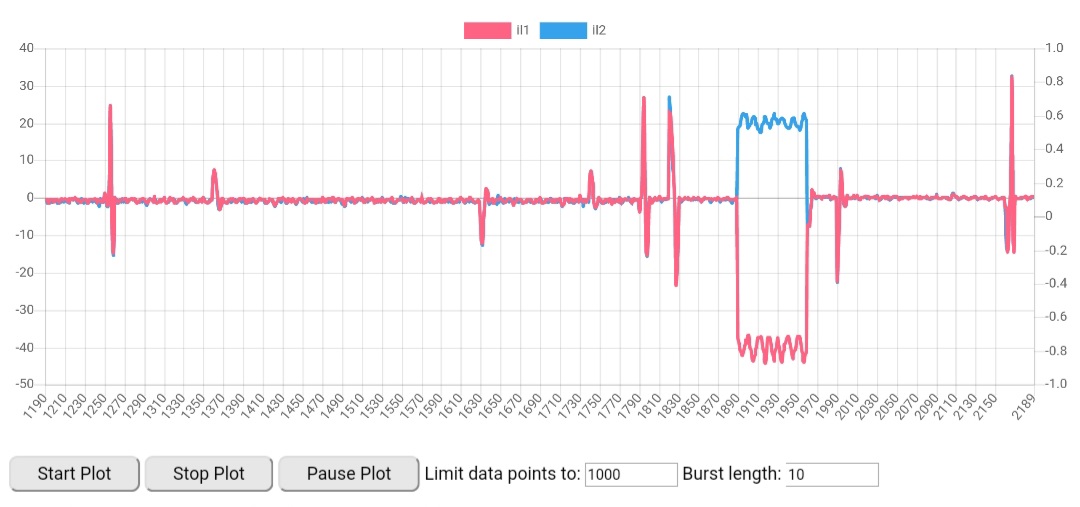
I think that is it. That shift is visible here. It appears instantly once I put manualid, and signal returns back when I stop manualid.Martin1775 wrote: ↑Mon Dec 14, 2020 8:22 pm I'm not shure what you mean with the signal shifting, it may be a interferenz from the magnetic field.

I desperately need to get the car drivable in the next few weeks. If I miss the deadline the project will essentially become a pile of scrap. All I need is to drive the the car few hundred meters up to 40 km/h. I will continue to search for options regarding encoder replacement. But if unsuccessful I need a plan B - I want to try and get the car to drive those few hundred meters with sine firmware. I got somewhat ok throttle response with max slip value however with 150 V of battery attached and throttle all the way the car does not drive fast enough. How can I get it to speed up? Which setting should I try? I can attach more battery modules that is not a problem if that would help? Or is that even possible? I think Johannes has tried to drive the car with sine?
-
arber333
- Posts: 3796
- Joined: Mon Dec 24, 2018 1:37 pm
- Location: Slovenia
- Has thanked: 166 times
- Been thanked: 413 times
- Contact:
Re: Help! Prius gen3 inverter using ABZ encoder
I am sorry to hear that.
Maybe you should see if you can get ACIM motor and drive the car with that. That would be way easier than your PM motor.
Or you can get one Outlander rear motor and just use its resolver. It works.
...
Maybe you should see if you can get ACIM motor and drive the car with that. That would be way easier than your PM motor.
Or you can get one Outlander rear motor and just use its resolver. It works.
...
-
m.art.y
- Posts: 715
- Joined: Sat Jun 06, 2020 6:54 pm
- Location: UK/EU
- Has thanked: 38 times
- Been thanked: 37 times
Re: Help! Prius gen3 inverter using ABZ encoder
Yes a bit sad. If I had more time that would not be a problem. But at the moment I just need to use the existing motor somehow. Motor does not make noises it is running pretty well except that it does not speed up enough - I added 200V of battery but speed is the same. Which setting I could try?
Would that resolver fit in the space I've got? Does it also need very tight mounting tolerances? It has to mounted over the shaft?
-
m.art.y
- Posts: 715
- Joined: Sat Jun 06, 2020 6:54 pm
- Location: UK/EU
- Has thanked: 38 times
- Been thanked: 37 times
Re: Help! Prius gen3 inverter using ABZ encoder
I got a replacement encoder and I am back on it. With R29 and R30 still removed I did try various voltage divider options and the results are:
With 16.4 kOhms (2× 8K2 in series) over C27 and C28 I measured ~ 0.9 V (might have been 1.1 V) at lowest and ~2.9 V at highest points.
I tried lower resistor values like 3K3, 6K8 and 8K2 but then the voltages peak to peak are lower.
Without any resistors attached (R29 and R30 still removed) the voltage at the highest measured at C27 and C28 is ~3.7 V and as I understand is too high if inverter expects a signal up to 3.3V?
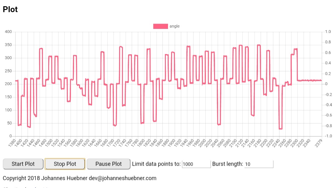
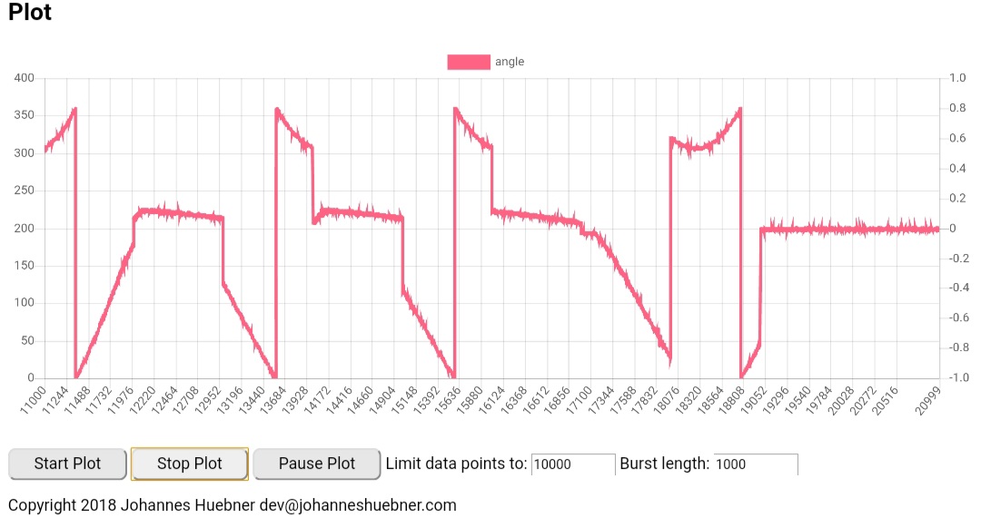
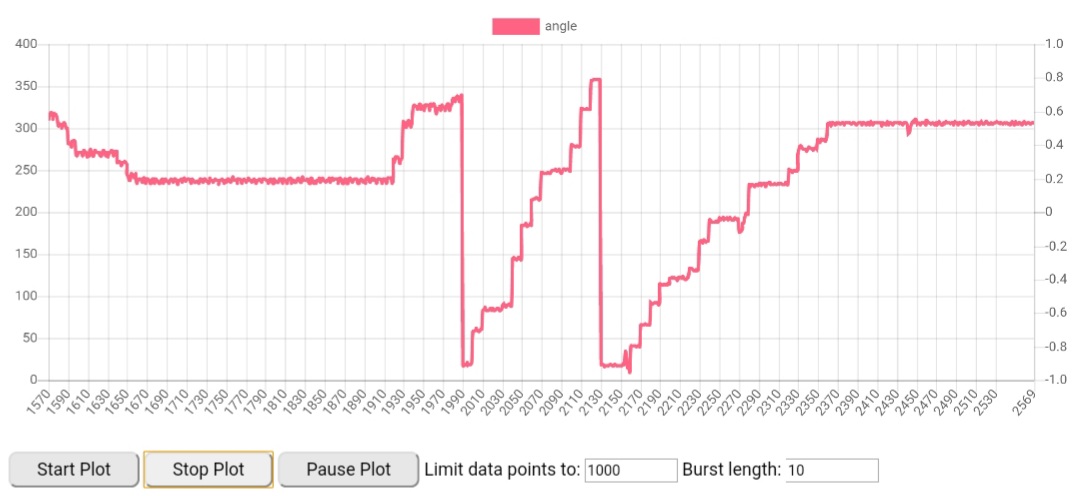
I did test the encoder not connected to the inverter and itself without any resistors it gives a signal from ~1.29V to ~4.9 V. I could see that sin and cos are shifted by 90 degrees. Encoder itself produces a sinusoidal signal where it goes up and down gradually - signal gradually goes up to 4.9 V and then graduaĺly in the same fashion start to go down till it reaches 1.3 V and starts going back up. I was able to measure it with a multimeter hooked up and I was slowly turning encoder body and magnet remained stationary - that gives way more control and precision when spinning it by hand as motor shaft is jumpy as it moves in steps - sometimes few steps straight one after another. When I also plotted the angle when spinning the encoder and not the magnet I got a nice angle curve:
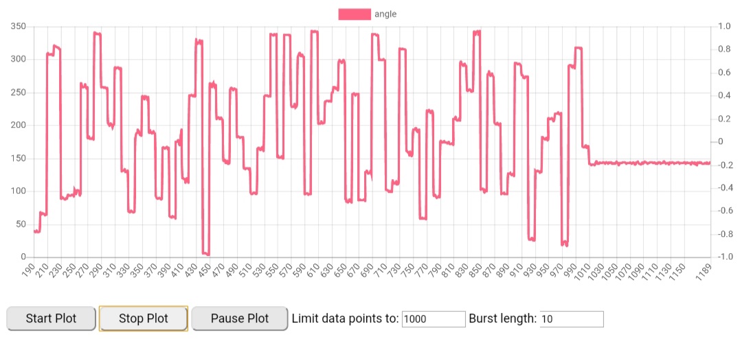
I cannot directly access the motor shaft to spin it after encoder is mounted as motor is on a gearbox as without a gearbox the motor 'sticks' together as motor end that attaches to the gearbox has no bearing and is centered by the gearbox itself. So I have to spin on the geabox drive shaft (wheel) and then it gives me a totally different angle plot curve:
However when I try to give it some manualid there is no movement of the motor only occasionally I get a little nudge forward and sometimes backward when I spin the motor to different positions by hand. Only I get a very strange sound from the motor. I did remove the encoder and tried to give motor some manualid just to observe it the motor shaft does anything at all and it moves couple mm, and then relaxes when manualid is stopped.
https://mega.nz/file/pppiHQKD#OJPC5zu54 ... Y_5bbOp8tc
Please can somebody listen to this and tell me if you heard this before when trying to spin your motor with FOC?
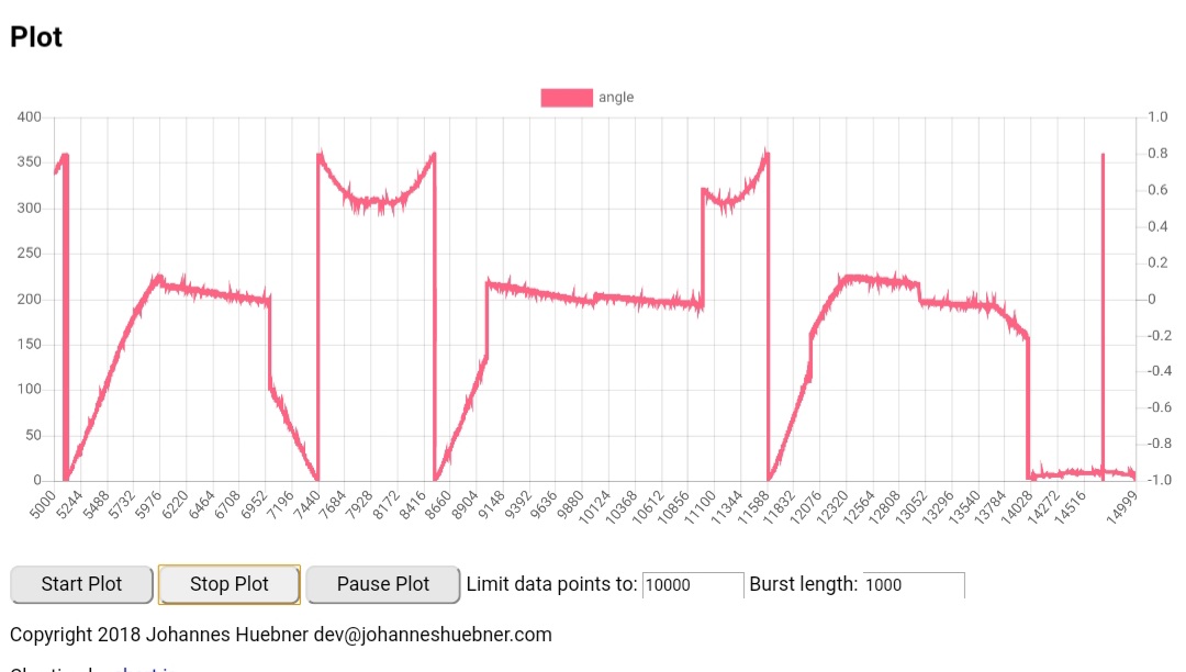
I did also see spikes and jitter on the angle curve at idle. I did try connecting the shield of the signal cable to inverter ground only, then I connected the shield to both inverter ground and the motor case. Inverter ground and inverter case are connected to each other and vehicle chassis as is the motor connected to vehicle chassis.
What else I can try? If anybody has any ideas can you please let me know?
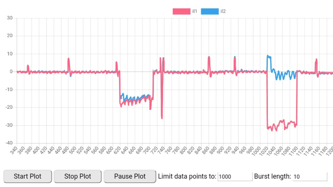
I do attach also some current sensor plots when I try to send the motor some manualid. Do these look normal?
EDIT:
I tried giving the motor up to 150A manualid. Occasionally I got strong attempt to rotate but very short and then it stops. Other times motor starts to vibrate at 150 A. Surely I should not need to go any higher?
With 16.4 kOhms (2× 8K2 in series) over C27 and C28 I measured ~ 0.9 V (might have been 1.1 V) at lowest and ~2.9 V at highest points.
I tried lower resistor values like 3K3, 6K8 and 8K2 but then the voltages peak to peak are lower.
Without any resistors attached (R29 and R30 still removed) the voltage at the highest measured at C27 and C28 is ~3.7 V and as I understand is too high if inverter expects a signal up to 3.3V?
I did test the encoder not connected to the inverter and itself without any resistors it gives a signal from ~1.29V to ~4.9 V. I could see that sin and cos are shifted by 90 degrees. Encoder itself produces a sinusoidal signal where it goes up and down gradually - signal gradually goes up to 4.9 V and then graduaĺly in the same fashion start to go down till it reaches 1.3 V and starts going back up. I was able to measure it with a multimeter hooked up and I was slowly turning encoder body and magnet remained stationary - that gives way more control and precision when spinning it by hand as motor shaft is jumpy as it moves in steps - sometimes few steps straight one after another. When I also plotted the angle when spinning the encoder and not the magnet I got a nice angle curve:
I cannot directly access the motor shaft to spin it after encoder is mounted as motor is on a gearbox as without a gearbox the motor 'sticks' together as motor end that attaches to the gearbox has no bearing and is centered by the gearbox itself. So I have to spin on the geabox drive shaft (wheel) and then it gives me a totally different angle plot curve:
However when I try to give it some manualid there is no movement of the motor only occasionally I get a little nudge forward and sometimes backward when I spin the motor to different positions by hand. Only I get a very strange sound from the motor. I did remove the encoder and tried to give motor some manualid just to observe it the motor shaft does anything at all and it moves couple mm, and then relaxes when manualid is stopped.
https://mega.nz/file/pppiHQKD#OJPC5zu54 ... Y_5bbOp8tc
Please can somebody listen to this and tell me if you heard this before when trying to spin your motor with FOC?
I did also see spikes and jitter on the angle curve at idle. I did try connecting the shield of the signal cable to inverter ground only, then I connected the shield to both inverter ground and the motor case. Inverter ground and inverter case are connected to each other and vehicle chassis as is the motor connected to vehicle chassis.
What else I can try? If anybody has any ideas can you please let me know?
I do attach also some current sensor plots when I try to send the motor some manualid. Do these look normal?
EDIT:
I tried giving the motor up to 150A manualid. Occasionally I got strong attempt to rotate but very short and then it stops. Other times motor starts to vibrate at 150 A. Surely I should not need to go any higher?
-
johu

- Site Admin
- Posts: 7182
- Joined: Thu Nov 08, 2018 10:52 pm
- Location: Kassel/Germany
- Has thanked: 552 times
- Been thanked: 1918 times
- Contact:
Re: Help! Prius gen3 inverter using ABZ encoder
Without proper angle feedback the inverter won't do anything meaningful. Only when you turn the motor by hand a get a good 0-360° angle plot does it make any sense to carry on.
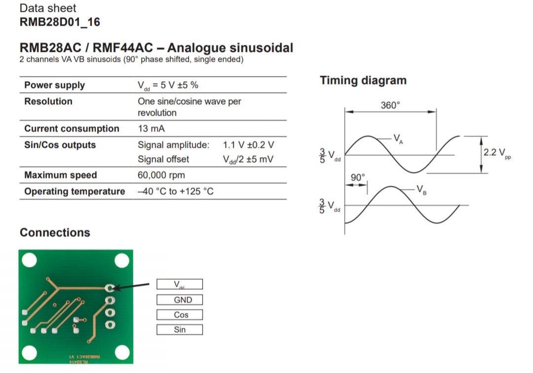
I don't know which sin/cos module you're using. The MLX90380 will center around 1.65V when supplied with 3v3. Maybe check if your sin/cos chip also runs from 3.3V
Otherwise mess around with the resistors to center around 1.65V. For example a signal between 0.65V to 2.65V
I don't know which sin/cos module you're using. The MLX90380 will center around 1.65V when supplied with 3v3. Maybe check if your sin/cos chip also runs from 3.3V
Otherwise mess around with the resistors to center around 1.65V. For example a signal between 0.65V to 2.65V
Support R/D and forum on Patreon: https://patreon.com/openinverter - Subscribe on odysee: https://odysee.com/@openinverter:9
-
m.art.y
- Posts: 715
- Joined: Sat Jun 06, 2020 6:54 pm
- Location: UK/EU
- Has thanked: 38 times
- Been thanked: 37 times
Re: Help! Prius gen3 inverter using ABZ encoder
I still have got this encoder:johu wrote: ↑Tue Dec 29, 2020 9:13 am Without proper angle feedback the inverter won't do anything meaningful. Only when you turn the motor by hand a get a good 0-360° angle plot does it make any sense to carry on.
I don't know which sin/cos module you're using. The MLX90380 will center around 1.65V when supplied with 3v3. Maybe check if your sin/cos chip also runs from 3.3V
Otherwise mess around with the resistors to center around 1.65V. For example a signal between 0.65V to 2.65V
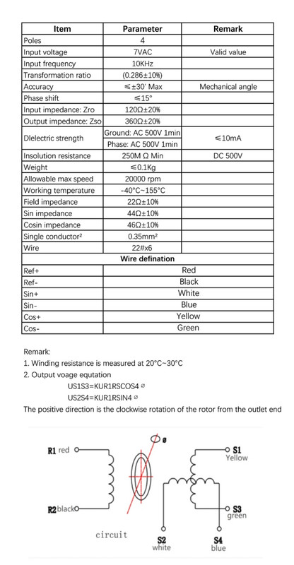
Also Johannes could you please take a look at this resolver. Would it work with your software? They said it can be supplied with less than 7 V. Just thinking to get this just in case I can't get the encoder working.
-
m.art.y
- Posts: 715
- Joined: Sat Jun 06, 2020 6:54 pm
- Location: UK/EU
- Has thanked: 38 times
- Been thanked: 37 times
Re: Help! Prius gen3 inverter using ABZ encoder
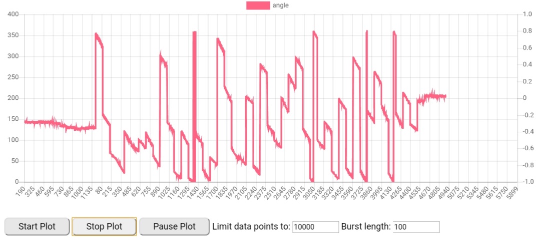
It spins!!!! I changed the encoder sin/cos wires around to be wrong on purpose just to try (cos to encA and sin to encB) and I noticed the attempt to rotate was slightly better but still no spinning. Then I changed resistors to 10 K and I could not believe my eyes it started to spin and kept going! But then I stopped it and it did not start again. But when I give it a little spin by hand it starts to spin again - not always but much more often than I have ever seen. Is this normal? Am I close now? Does it always need to start spinning if syncoffs is still set at 0? Here is an angle plot I captured when motor was spinning by itself.johu wrote: ↑Tue Dec 29, 2020 9:13 am Without proper angle feedback the inverter won't do anything meaningful. Only when you turn the motor by hand a get a good 0-360° angle plot does it make any sense to carry on.
I don't know which sin/cos module you're using. The MLX90380 will center around 1.65V when supplied with 3v3. Maybe check if your sin/cos chip also runs from 3.3V
Otherwise mess around with the resistors to center around 1.65V. For example a signal between 0.65V to 2.65V

-
johu
- Site Admin
- Posts: 7182
- Joined: Thu Nov 08, 2018 10:52 pm
- Location: Kassel/Germany
- Has thanked: 552 times
- Been thanked: 1918 times
- Contact:
Re: Help! Prius gen3 inverter using ABZ encoder
Well you maybe closing in on the sweetspot where the signals are centered at 1.65V. Keep going 
The resolver you mention will work.
The resolver you mention will work.
Support R/D and forum on Patreon: https://patreon.com/openinverter - Subscribe on odysee: https://odysee.com/@openinverter:9
-
Martin1775
- Posts: 43
- Joined: Fri Nov 01, 2019 9:39 pm
- Location: Ochtrup Germany
Re: Help! Prius gen3 inverter using ABZ encoder
With the voltage you get without resistor, I expect the center is at 3,1V, so too reach the center at 1,65V the resistor parallel to C27/C28 should be around 11,5kOhm. By calculation you get an output voltage between 0,69 and 2,62V with this value and that fits with the calculation by your measurement at 16,4kOhms (0,9V to 2,9V).
From the diagram the center is at 3V, if your supply voltage ist 5V, that results in a value of 12,3kOhm.
It may be a little tricky to get the right value, but I think when you slowly rotate the motor and the angle changes smooth with the rotation it will work.
I wish you every success with the adjustment.
-
arber333
- Posts: 3796
- Joined: Mon Dec 24, 2018 1:37 pm
- Location: Slovenia
- Has thanked: 166 times
- Been thanked: 413 times
- Contact:
Re: Help! Prius gen3 inverter using ABZ encoder
Well good! The symptoms now are one of resolver off its angle.m.art.y wrote: ↑Tue Dec 29, 2020 1:46 pm It spins!!!! I changed the encoder sin/cos wires around to be wrong on purpose just to try (cos to encA and sin to encB) and I noticed the attempt to rotate was slightly better but still no spinning. Then I changed resistors to 10 K and I could not believe my eyes it started to spin and kept going! But then I stopped it and it did not start again. But when I give it a little spin by hand it starts to spin again - not always but much more often than I have ever seen. Is this normal? Am I close now? Does it always need to start spinning if syncoffs is still set at 0? Here is an angle plot I captured when motor was spinning by itself.
Now you can try to perform procedure for syncoffset to find where encoder is pointing to. Then you will be able to rotate motor with direct control.
Was the motor running smoothly or was it rumbling?
-
m.art.y
- Posts: 715
- Joined: Sat Jun 06, 2020 6:54 pm
- Location: UK/EU
- Has thanked: 38 times
- Been thanked: 37 times
Re: Help! Prius gen3 inverter using ABZ encoder
It was running smoothly it seemed and only with 20-30 of manualid. And it was running faster than I was ever able to get it to spin with sine firmware. The issue still is that it does not always start to spin and you have to move the shaft to a different position to get it to spin again. I did find a spot after rotating the encoder itself to different position where it started to spin every time as many times I tried it. Tried to search for syncoffs but there seemed to be too wide of the range where the motor did not spin I could not narrow it down and the motor was spinning backwards. I tried to use the throttle in run mode couple times and I got a run away motor. I will do more experimentation with resistor values tomorrow.arber333 wrote: ↑Tue Dec 29, 2020 7:38 pm Well good! The symptoms now are one of resolver off its angle.
Now you can try to perform procedure for syncoffset to find where encoder is pointing to. Then you will be able to rotate motor with direct control.
Was the motor running smoothly or was it rumbling?
 But at least there is progress as I was starting to think it will never run..
-
m.art.y
- Posts: 715
- Joined: Sat Jun 06, 2020 6:54 pm
- Location: UK/EU
- Has thanked: 38 times
- Been thanked: 37 times
Re: Help! Prius gen3 inverter using ABZ encoder
I'm happy to say that I got it working today. It was a matter of finding the right resistor values. I tried 11.5 kOhm, then 11.9 kOhm with no change. Then I put in 12.6 kOhm and immediately I noticed that motor was spinning up much faster and with even less manualid. From there finding syncoffs was a breeze according to extremely helpful video tutorial from Damien and Johannes. Motor seems to be running smoothly and responds well to throttle in both directions with wheels off the ground. At full speed with 300V battery current sensors are reporting around 150 A.Martin1775 wrote: ↑Tue Dec 29, 2020 7:20 pm From the diagram the center is at 3V, if your supply voltage ist 5V, that results in a value of 12.3kOhm.
I would like to use the opportunity and express my gratitude to arber333 for recomending the correct encoder - it was a good option because it comes in ready to use package and it was a matter of mounting it on. Also would like to thank Johannes and Martin1775 for helping to make it work - I wouldn't have been able to figure that bit on my own. Thank you guys!

-
m.art.y
- Posts: 715
- Joined: Sat Jun 06, 2020 6:54 pm
- Location: UK/EU
- Has thanked: 38 times
- Been thanked: 37 times
Re: Help! Prius gen3 inverter using ABZ encoder
So I had first test driving the car. I have 280 V on the HV battery. Most of the other parameters are default. It is hard to pull from a standstill, sometimes the car does not even want to move. However when it gets going it seems to pull and pick up speed. What settings I could try to get it pull from a standstill a bit better? I regret not adding a bit more HV battery while I had a chance but too late now.
-
johu
- Site Admin
- Posts: 7182
- Joined: Thu Nov 08, 2018 10:52 pm
- Location: Kassel/Germany
- Has thanked: 552 times
- Been thanked: 1918 times
- Contact:
Re: Help! Prius gen3 inverter using ABZ encoder
Ah, missed your success message - you're welcome
Not sure about the standstill issue as there's no such thing like boost in the sine firmware. Whats your throtcur?
Not sure about the standstill issue as there's no such thing like boost in the sine firmware. Whats your throtcur?
Support R/D and forum on Patreon: https://patreon.com/openinverter - Subscribe on odysee: https://odysee.com/@openinverter:9
-
m.art.y
- Posts: 715
- Joined: Sat Jun 06, 2020 6:54 pm
- Location: UK/EU
- Has thanked: 38 times
- Been thanked: 37 times
Re: Help! Prius gen3 inverter using ABZ encoder
My throtcur is 1.3. When I put it to 2, I think I felt better performance but current sensors were reporting ~200 A when I tried to drive. I am not sure if that is normal but I thought 200 A is high when just starting to move. It feels like it's struggling to respond to throttle till it get's going. I can feel some vibration or something slightly when just trying to pull from standstill. Previously my motor was run at ~400 V, now I only got 280 V. I knew the top speed was only 50 km/h with that voltage I just did not realize there will be starting to drive issues when actually pulling the car. With wheels of the ground seemed to be ok. Any other settings I could try to achieve more torque to pull away? I don't care if I lose speed at the moment. I am using singleregen by the way as I only connected one channel of the throttle pedal.
-
johu
- Site Admin
- Posts: 7182
- Joined: Thu Nov 08, 2018 10:52 pm
- Location: Kassel/Germany
- Has thanked: 552 times
- Been thanked: 1918 times
- Contact:
Re: Help! Prius gen3 inverter using ABZ encoder
Sorry I forgot, is it a gen2 or gen3 inverter? What motor is it?
Also it is normal for current to be high. Torque needs current no matter if at standstill or at speed. I'm running the Leaf motor at 450A, some run it at 650A (throtcur 6.5).
Also it is normal for current to be high. Torque needs current no matter if at standstill or at speed. I'm running the Leaf motor at 450A, some run it at 650A (throtcur 6.5).
Support R/D and forum on Patreon: https://patreon.com/openinverter - Subscribe on odysee: https://odysee.com/@openinverter:9
-
arber333
- Posts: 3796
- Joined: Mon Dec 24, 2018 1:37 pm
- Location: Slovenia
- Has thanked: 166 times
- Been thanked: 413 times
- Contact:
Re: Help! Prius gen3 inverter using ABZ encoder
I think you may try 400A which is current only motor is seeing. Phase current. If that current will be seen by battery you have to develop some RPM and possibly go to FW region. Your motor seems rather small. What is its power rating?
A
A